")
Back to Journals » Research Reports in Clinical Cardiology » Volume 10
Computational modeling of balloon-expandable stent deployment in coronary artery using the finite element method
Authors Umer M, Najabat Ali M , Mubashar A , Mir M
Received 10 May 2018
Accepted for publication 25 August 2018
Published 6 September 2019 Volume 2019:10 Pages 43—56
DOI https://doi.org/10.2147/RRCC.S173086
Checked for plagiarism Yes
Review by Single anonymous peer review
Peer reviewer comments 2
Editor who approved publication: Dr Richard Kones
Muhammad Umer, Murtaza Najabat Ali, Aamir Mubashar, Mariam Mir
Biomedical Engineering & Sciences Department (BMES), School of Mechanical and Manufacturing Engineering (SMME), National University of Sciences and Technology (NUST), Islamabad, Pakistan
Correspondence: Murtaza Najabat Ali
Biomedical Engineering & Sciences Department, School of Mechanical and Manufacturing Engineering (SMME) National University of Sciences and Technology (NUST), Sector H-12, Islamabad, Pakistan
Tel +929 085 6053
Email [email protected]
Introduction and purpose: For the implantation of a small mechanical supporting device such as a stent, angioplasty is a more reliable technique to regain the perfusion along the heart vessel. This research work demonstrates a relative study for two different stent models during implantation in coronary artery. The purpose of this analysis was to explore the clinical efficiency of a balloon expandable stent deployment employing the finite element method.
Methods: The two different models included are the Cypher Bx Velocity® (Bx_Velocity; Johnson & Johnson Corporation, New Brunswick, NJ, USA) and Savior (ST Flex Pro; National Engineering and Scientific Commission, Islambad, Pakistan). As the majority of stents are deployed using an angioplasty balloon guided by a catheter-shaft, in this study, the delivery of stents was governed by a sophisticated balloon of a trifolded pattern, attached to the catheter-shaft. This configuration has often been neglected in the past due to the complexity of interaction and the limitation of computational power.
Results: The use of a trifolded semi-compliant balloon gives more promising results for quantification with experimental data available from the manufacturer’s compliance charts. This type of relative study allows us not only to improve the design of the available stent model, but also helps in probing the integrity of newly suggested models and reduces certain risks associated with the angioplasty technique. The following factors, such as stent expansion, foreshortening, dog-boning, elastic recoil, and the distribution of equivalent stresses were used to compare and improve the clinical outcome of the available stent models.
Conclusion: The validation of numerical study for the Bx_Velocity stent was made with the manufacturer’s compliance chart data and for the Savior Stent with a report of experimental work data from NESCOM. Finally, some suggestions were made for good deliverability and reliability based on the above design criteria.
Keywords: stent, finite element method, trifolded balloon, foreshortening, open-deployment, confined-deployment
Introduction
Coronary artery disease (CAD) which leads to heart attack is one of the major causes of death around the globe. CAD is due to the occurrence of atherosclerotic plaque inside the coronary artery which supplies oxygenated blood and energetic micro-nutrients to the heart tissues. There are number of factors which cause the growth of plaque such as high cholesterol, hypertension, smoking, and diabetes.1,2
A coronary artery stent is a spring type minute mesh tube, typically made of metal alloys which are most commonly used to treat stenosed blood vessels feeding the heart tissues. If a clot forms and fully blocks blood flow to the heart muscles, this leads to a heart attack immediately. The cause is the fat deposition on the interior wall of the blood vessel, narrowing the passage for blood flow, causing severe chest pain. The process of deposition and coronary artery blockage is known as atherosclerosis. It consists of plaque formation in the arterial walls due to lipids/cholesterol which grows larger and later results in occlusion of the artery, termed as stenosed artery.3,4
To avert this problem, a less invasive treatment was introduced in the early 1980s, known as percutaneous trans-luminal coronary angioplasty or PTCA.5,6 In this treatment, an angioplasty balloon is inserted through the femoral artery all the way up to the affected region. Once the target region has been reached, the balloon could be inflated to compress the lesion tissue alongside the artery wall to gain luminal shape and restore the oxygenated blood flow. But due to the plaque's hyper-elastic behavior, re-narrowing of the vessel was very common until the 1990s when a small mechanical scaffolding device called a stent was introduced in order to avert the recoiling problem of stenosed artery.7,8 This device is made of metal such as stainless steel and undergoes a large amount of plastic deformation during the deployment procedure which means a huge amount of stresses while holding the blood vessel firmly open and permanently under the pulsatile flow condition of blood for at least 10 years of fatigue life according to FDA requirement.9 This scaffolding device provides a better mechanical brace in keeping the artery opened subsequently to the balloon angioplasty. In most cases, the stent is crimped on a folded balloon in order to allow a good deliverability in the low cross-sectional profile of the vessel. Once the catheter assembly is inserted into the stenosed artery, the balloon is inflated gradually to 5–6 bars of pressure, in order to gain the targeted deployment diameter. Upon deflation the catheter along with the balloon is withdrawn and the stent stays there permanently after a small recovery.10 In recent years, a number of researchers have worked on stent deployment technique using numerical computational approach in many different ways such as open-deployment including; Dumoulin11 (2000), Etave12 (2001), Migliavacca13 (2002), Chua14 (2003), Petrini15 (2004), Migliavacca16 (2005), Hall17 (2006), Wang18 (2006), De Beule19 (2008), Lim20 (2008), Jovicic21 (2014) and confined-deployment (considering artery as well); Gervaso10 (2008), Chua22 (2004), Lally23 (2005), Liang24 (2005), Holzapfel25 (2005), Bedoya26 (2006), Gijsen27 (2008), Capelli28 (2009), Pericevic29(2009), Martin30 (2013), Mortier31 (2014), and Zhao and Gu32 (2014). In these studies, a number of assumptions has been made such as the loading condition, ignoring the folded pattern of the balloon, its attachment to the catheter shaft and multi-layers of artery etc. In most of the cases, a cylindrical surface has been considered for the stent expansion with displacement driven conditions. Such simplification does not allow the validation of experimental free or arterial pressure deployment curve. Furthermore, the deployment process is highly transient; assuming it as a static solution can essentially alter the final results.
In order to increase the stent durability and performance under the severe conditions of pulsation and hemodynamic impacts, the stent design must be highly sophisticated. Computational mechanics play an exceptional role in providing an ideal design for a stent particularly when physical testing is demanding due high cost and extreme size. The numerical simulation gives numerous options in different circumstances, addressing a variety of designs, schemes and materials, to estimate in terms of radial strength, deliverability, profile, compatibility, flexibility and life time integrity, even before implementing the actual engineering practice. In addition to this pre-processed information revealed by the numerical simulation, computational approach is also useful for comparison of different existing physical models. With all the information in hand, engineers and physicians can make a better decision on the enactment comparison of the investigated designs, particularly to decide what deployment procedure and which stent to use for which clogged blood vessel.
Vessel injury is a common threat during stent deployment. The non-uniform expansion of stents (dogboning) has proved to be one of the main causes of lumen damage. Sharp hinges and thin struts resulting from poor design is also accountable for vessel injury.33 From the Endoprosthesis survey, the rate of restenosis was found to be 20–50%, which is the re-occurrence of obstruction in the treated coronary artery.34 It has been claimed that, such a huge discrepancy in the rate of restenosis is due to the difference in geometrical parameters and the design of the stent. The contraction in the axial direction known as fore-shortening, with radial expansion is also responsible for restenosis.27
In this study, the deployment of stents was governed by a trifolded angioplasty balloon, attached to the catheter shaft at distal ends. Such configuration enables the examination of the stent expansion behavior more realistically. In particular, the validation of in-vitro test data for a newly commercialized Savior Stent. Alternatively, a comparison was also made with a well-known Cypher Bx_Velocity® (Bx_Velocity) stent model. Two sets of simulation were run for each model, (1) open-deployment; and 2) confined-deployment. Both configurations were pressure-driven conditions, based on the inner surface of the folded balloon. The computational results were compared quantitatively with experimental data from the manufacturers, using the pressure-diameter correlation. Such study helps in evaluation and comparison of the newly developed stent design, to improve the mechanical and physical properties along with good clinical efficiency and extraordinary deliverability. Ultimately this paper suggests an optimal approach for the stent deployment methodology using the finite element method.
Materials and methods
The first step for any finite element analysis is the geometry of instances, followed by meshing, material assignment and boundary conditions. Commonly, a finite element analysis of a stent is accompanied by a geometrical model, a material model, meshing, interaction properties, boundary and load condition implementation during stent deployment. The success and failure of the simulation is described by these prerequisite suppositions.
In the present simulation work, two different configurations of numerical analysis were carried out, implementing FEA product suite Abaqus.6.14 (Simulia-Corporation). Abaqus gives influential and comprehensive solutions for many sophisticated and routine technical problems. The geometrical models of stents, in two different deployment configurations; open-deployment (artery exclusion) and the confined-deployment (artery inclusion) have been considered. Each setup of analysis employed the pressure-driven loading condition on a trifolded balloon membrane.
Geometries and discretization
Two balloon expandable stents were considered for the investigation and comparison purposes; namely the Bx_Velocity stent (stent-A, Johnson & Johnson Corporation, New Brunswick, NJ, USA), and the Savior Stent (stent-B, ST Flex Pro, NESCOM, Pakistan) as shown in Figure 1. Initially the 3D CAD geometries were modeled using solid modeling packages such as Pro-Engineering Wildfire v5.0 (Parametric Technology Corporation, Boston, MA, USA) and Solidworks (Dassault Systèmes,Vélizy-Villacoublay, France). These three geometries were than imported into ABAQUS v6.14 (Dassault Systèmes, Simulia Corporation, Johnston, RI, USA). The configuration of Planner coordinate system was transferred into cylindrical coordinate system such that x, y and z represent the radial, circumferential and longitudinal direction respectively. Stent-A has circumferentially thicker sinusoidal strut segments, and each strut crown linked by N-shape bridge elements. Stent-B has a thinner sinusoidal strut alignment, which are liked by integral sign bridge at the quarter of the strut length rather than at crowns. The major difference lies in the linkage of the sinusoidal struts and its thickness. Both stent-A and stent-B have a crimped-diameter approximately of 1 mm when mounted on the balloon which gives a nominal length, and diameter of 8 mm and 3 mm respectively, as shown in Figure 2.
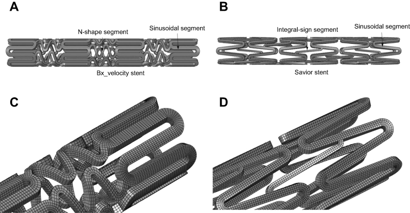 |
Figure 1 3D CAD geometries of stents and the compatible mesh model: Bx_Velocity stent (A); Savior Stent (B).Abbreviation: Bx_Velocity, Cypher Bx Velocity®. |
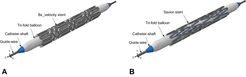 |
Figure 2 Assembled geometrical models of free deployment configuration in the crimped position along with the delivery system: including tapered folded balloon and catheter shaft: (A) Cypher Bx Velocity® stent; (B) Savior Stent. |
Mesh density was verified using mesh sensitivity analysis. Simulation was run for different numbers of elements ranging from 9,500 to 151,000. The results demonstrate mesh independency for both maximum Von Mises and radial stresses at discretized 55,252 for stent-A and 48,075 for Stent-B, reduced integration continuum elements (C3D4R).
A trifolded angioplasty balloon configuration as shown in Figure 3A, suggested by De Beule et al,19 who simplified the balloon geometry from micro-CT images, was considered for both stent deployments. In this analysis, the balloon membrane attachment to the guide-wire shaft was considered giving a tapered geometrical configuration less than 1 mm. The angioplasty balloon is based on nylon material, and provided with a compliance chart from the manufacturer to describe the pressure-diameter relationship based on in-vitro experimental results. Prior to deflation, the unfolded diameter is 3 mm. A trifolded deflated configuration reduces the diameter to 0.6 mm (inner) and 0.9 mm (outer). A length of 10 mm was assigned resulting in 1 mm overhang on each side, and a thickness of 0.02 mm. The balloon geometry was meshed, using 10,646 reduced integration membrane elements denoted as (M3D4R). The catheter shaft on which the balloon is mounted, is usually poly-ethylene material based, while the guide-wire, supporting the shaft is usually made of stainless steel or nitinol material. Both of these were discretized into 5,872 reduced-integration linear hexahedral elements of type C3D4R. The shaft diameter was 0.6 mm and a length of 12 mm. The guide wire was 0.5 mm in diameter and 14 mm long (Table 1).
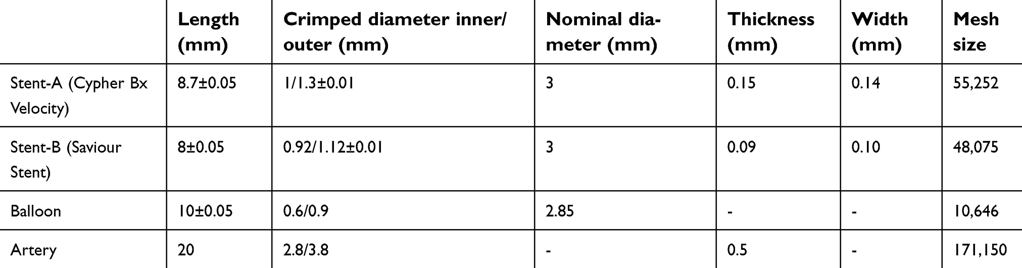 |
Table 1 Details of geometrical parameters for both models: stent-A and stent-B |
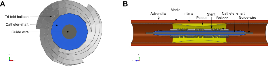 |
Figure 3 Cross-sectional view of the folded balloon attached to the catheter proir to inflation (A) and assembled model of confined-deployment configuration, atherosclerotic plaque and artery (B). |
A stenotic artery composed of three discrete layers with dispersed atherosclerotic plaque in the mid-section as shown in Figure 3B was simulated in a tubular shape with cylindrical coordinate system. The length of artery, internal and external diameter of 20, 2.8 and 3.8 mm was assigned respectively, which gives a constant thickness of 0.5 mm along its length. The three different layers were composed of intima, media and adventitia carrying thicknesses of 0.145, 165 and 0.19 mm, respectively. These parameters were according to the report from experimental results by Holzapfel et al.35 The atherosclerotic plaque was modeled in such a way that causes 55% depletion in the blood flow cross-sectional area. The mid-region thickness of plaque was 0.4 mm in a semi-elliptical shape using a base length of 8 mm. The artery layers and plaque collectively were discretized into 171,150 reduced-integration continuum elements (C3D8R).
Constitutive material model
Any stent during deployment undergoes a substantial plastic deformation with a small elastic recovery. The stents under consideration are fabricated from medical grade 316L stainless steel. In the current study, a rate independent Von Mises yield criterion was used, to define the elastic-plastic mechanical response. The stress-strain curve for 316L stainless steel meshed tubular shape was acquired from ultimate tensile test data suggested by Minitubes.36 To describe the elastic behavior of stent material, a Young’s modulus of 193 GPa, yield strength of 360 MPa, an ultimate tensile strength of 675 MPa, Poisson’s ratio of 0.29 and the material density of 7950 kg/m3 was assigned.
The balloon is usually fabricated either from polyethylene terephthalate or nylon material. The true stress-strain curve was approximated by assuming a linear elastic model with Young’s modulus of 920 MPa, Poisson’s ratio of 0.4 and material density of 1100 kg/m3. Such assumption for angioplasty balloons was based on a study by De Beule et al,19 who studied the impact of folded balloon on stent deployment implementing the finite element method.19
The material model selection for a highly non-linear mechanical behavior of artery, each individual layer and the atherosclerotic plaque is considered to be the most perplexing task and debatable. Different hyper-elastic models are being suggested by different researchers throughout the literature. The most commonly used isotropic models are Neo-Hookean, Mooney-Rivlin, the Ogden model and the Holzapfel model defined in Abaqus/CAE. The first two are the simplest and used with a limited amount of deformation. On the other hand, the Ogden model is the more powerful and flexible model, expressed by Principal Stretch ratio rather than invariants of the left Cauchy-Green tensor of deformation.37
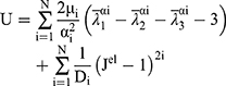
The current analysis is based on the 3rd order and 1st order of the Ogden model for artery and plaque, respectively. To describe the discrete artery layers and atherosclerotic plaque behavior, the material parameters were selected based on the study of Holzapfel et al,35 who determined the mechanical properties for human coronary non-atherosclerotic artery,35 and Loree et al,38 who determined the modulus of human atherosclerotic plaque.38 The stress-strain relations for plaque, intima, media and adventitia based on hyper-elastic models plotted using material constants as shown in Figure 4.30 The Ogden strain energy general model potential is given by:
(1)
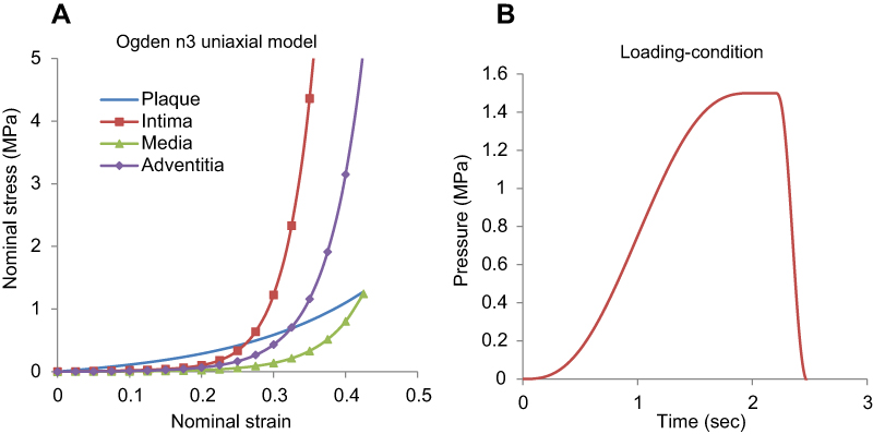 |
Figure 4 Artery layers and plaque constitutive material behavior, showing nominal stress-strain curves (A) and applied pressure amplitude curve with respect to time (B).Note: n3: Ogden model with N=3, uniaxial test data only. |
Where (2) ,
,  and
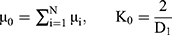
and  are the deviatoric principal stretches; N is the material parameter; and αi and Di are the temperature-dependent material constants. The initial shear modulus (µ0) and bulk modulus (K0) for Ogden model can be expressed as:
The Ogden strain energy potential can also be expressed to describe the Mooney-Rivlin and neo-Hookean forms for special choices of µi and αi.39
Boundary and loading conditions
The inflation of the trifolded angioplasty balloon was achieved through pressure-driven conditions. The radial displacement of the stent was triggered by the pressure application on the inner surface of the folded balloon. The loading condition utilizes an amplitude of smooth step of 2.5 sec in the pressure application. A pressure of 1.5 MPa was applied on the interior of the balloon, for a duration of 2 seconds. It was held constant for 0.2 seconds and reduced to −0.01 MPa at the end of the step to allow the elastic recoil as shown in Figure 4B. The same boundary conditions were used for both stents configuration during free and arterial deployment set. The extreme edges of the folded balloon membranes were attached to the shaft and the catheter wire ends were fixed in all directions. The stent movement was allowed in the radial direction and constrained axially at three circumferential nodes in the mid-section. The extreme ends of the artery were encastre using symmetry boundary condition. A node set for the stent was defined in the longitudinal direction for measuring the overall average diameter expansion.
Numerical aspect
The phenomenon of balloon-stent expansion is highly non-linear and dynamic accompanied by a large amount of deformations. To investigate such effect, Abaqus/Standard is limited not only due to complex interactions which leads to stop and slip conditions hence the solution can’t be fully converged but it also excludes the involvement of time dimension. Therefore, it is highly recommended to use Abaqus/Explicit solution method to analyze folded balloon inflation for more realistic results. However, the convergence problem of such a solution technique arises due to the inertia effect if the time interval for the pressure increments is too small which leads to instability. To acquire quasi-static solution, the time interval of expansion was kept as long as 2.5 seconds. But due to the lack of computational power, it is time consuming. To reduce the computational time the “mass scaling” technique was used. It is the addition of artificial mass-density, which helps to get a more economical solution in the close spell of physical expansion time hence a quasi-static solution could be achieved. According to the recommendation of ABAQUS v6.14 online documentations, an optimum scale factor of 20 was selected for semi-automated mass scaling technique.39 Further, the inflation of the balloon involves high interactions with itself and other materials such as stent, artery and plaque. This complex interaction is solved using Abaqus/Explicit general contact algorithm. The Coulomb friction model was used to define the friction behavior among different interaction surfaces, approximating the fraction coefficient to 0.2. To regulate the inertial effects under an acceptable range, throughout simulation the Kinetic energy of the solution was kept far below 5% to that of the internal energy.
Results and discussion
In this study, a numerical analysis was conducted implementing the finite element method, to investigate the impact of trifolded rapid balloon inflation on two different types of stent geometries. In each setup the balloon was attached to a catheter shaft giving a tapered configuration at the tip edges. Such studies help to evaluate some of the important short-term aspects such as dog-boning and foreshortening which play a vital role in the long-term stent-restenosis. Dog-boning is the pre-expansion of stents at the extremities and is dominant during the first few increments of pressure. Such non-uniform glass-hour-like shape during the initial stage is very common with angioplasty balloons and has been observed experimentally as well. Upon further incrimination in pressure, the dog-boning soon disappears and the stent reaches its uniform nominal cylindrical shape. The required computational running time for free deployment and confined-deployment was recorded as 36.5 and 49.5 hours for stent-A and 28 and 42.3 hours) for stent-B, respectively.
open-deployment
The stent deployment position at three levels of pressure is shown in Figure 5. A node set was defined along the length of the stent at discrete hinges in order to validate a relationship between pressure-diameter with manufacturer’s compliance experimental results for both stents. As shown in Figure 6, the curve consists of three different plateaus. Initially, at low pressure below the yield strength of the stent, at such loading there is almost no distortion. Further on, slight increments lead to high deformation giving a high slope (mid-plateau) which shows a rapid expansion beyond the yield point and the material goes under permanent deformation. At this pressure the balloon is fully inflated having a diameter of almost 3 mm. The final-plateau results from elastic stretch of the balloon membranes at high pressure showing a practically significant relation. Such relation between pressure and diameter helps to validate the model for a semi-compliant balloon. It is noticeable that the balloon inflation results from the folded pattern, while there is a little elastic stretch of the membranes at the end of the step. Comparing the two computational curves, an important conclusion can be deduced. Stent-A starts the rapid expansion at 0.45 MPa, while stent-B expands at a much lower pressure of 0.22 MPa, showing improved flexibility. This is due to the thinner stent design, which gives an improved deliverability and ease of access to a complex lesion profile. The computational curve is straighter compared to the experimental curve especially in the case of stent-B. This small discrepancy in the curve overlays is a result of the simplification of the material model as pure elastic for balloon membranes. In addition, the experimental data was plotted using a limited number of points, reduceing the trend to trace the exact true curve path.
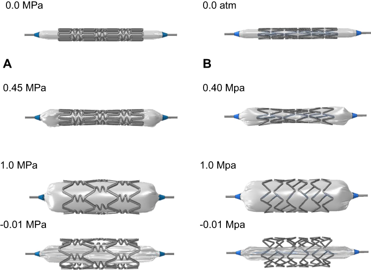 |
Figure 5 Transient expansion of open-deployment configuration at four different stages of pressure for each stent: Bx_Velocity (A); Savior (B). Abbreviation: Bx_Velocity, Cypher Bx Velocity®. |
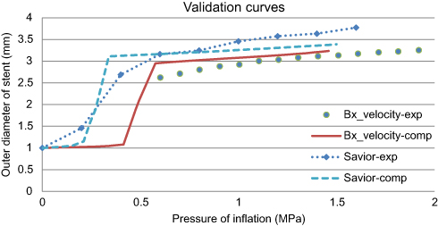 |
Figure 6 Relationship between pressure of inflation and stent diameter curves; a validation of computation (comp) results with experimental (exp) data during open-deployment of stent.Abbreviation: Bx_Velocity, Cypher Bx Velocity®. |
Stresses distribution
Figure 7A shows an open-deployment stresses distribution map for Von Mises for stent-A, and stent-B after the unloading step. The maximum stresses values of Von Mises σ, radial σr, hoop σθ and longitudinal σz stresses were recorded and are shown in Table 2. Due to the thinner strut design and diagonal-bridges in Stent-B, the peak equivalent stress was recorded 15% higher. The critical values were found at the crown of sinusoidal struts for stent-A, and at the crown of integral sign bridge linkage for Stent-B model. Such regions endure a large deformation and are responsible for the device flexibility. These results reveal that the reduction in the volume of foreign material leads to high stresses. Therefore, it is recommended that a material with high yield strength is desirable for thinner struts in order to increase the radial stiffness and safety factor. On the other hand, low yield strength and high ductility for thicker struts is vital to improve the expansion and descent flexibility.
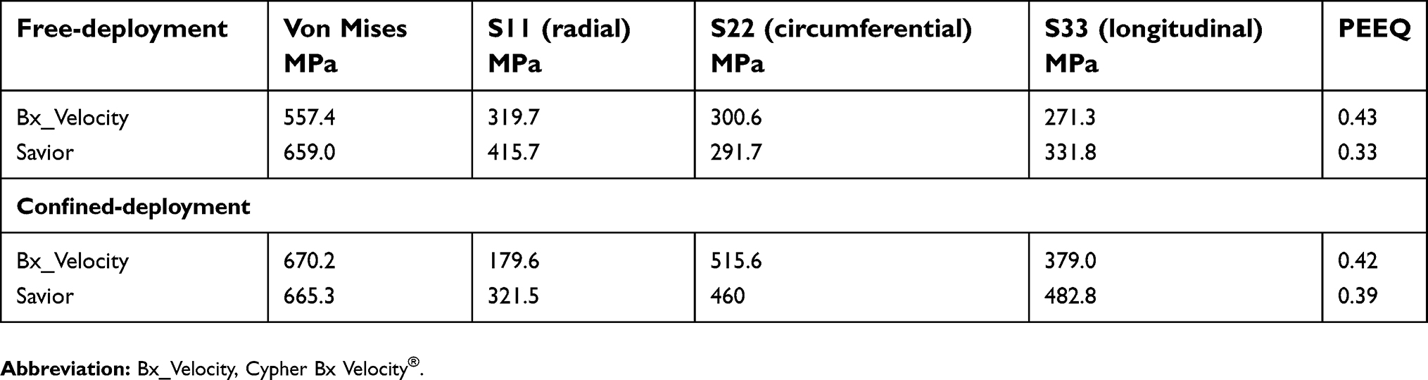 |
Table 2 Destribution of equivalent, radial, hoop and longitudnal peak stresses for both stents subsequent to their open- and confined-deployment |
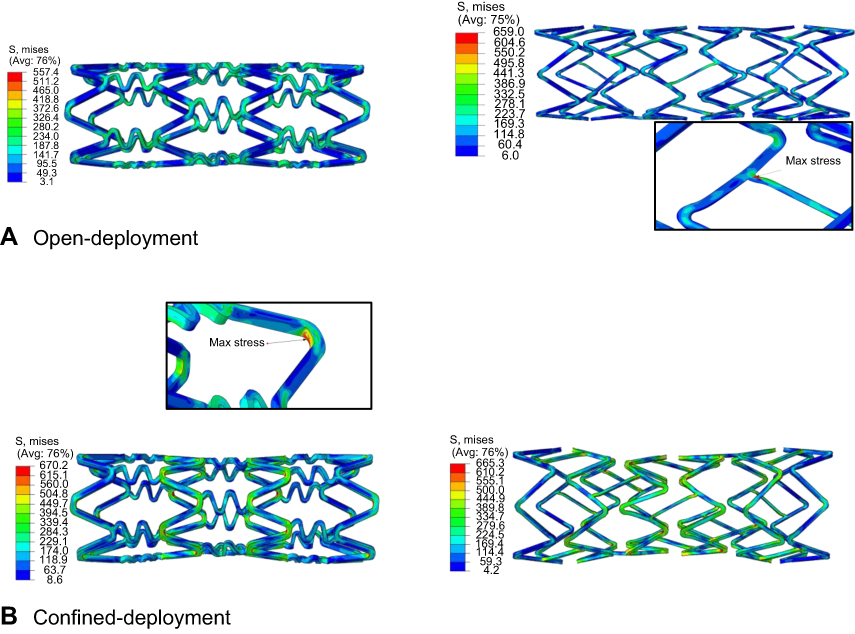 |
Figure 7 Von Mises stress destribution map comparison for unloaded open-deployment (A) and unloaded confined deployment (B). |
Foreshortening
Due to positive Poisson’s ratio and mesh tube design, a reduction occurs in the longitudinal direction as the stent expands in the radial direction. Such a phenomenon is named as “foreshortening” in stent deployment. Mathematically this term can be defined as:
(3)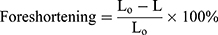
Where L0 is the length during cramped position; L is the length after the stent deployment. To see the short-term effect of folded balloon on different stent deployment, the resulting foreshortening, dog-boning and radial recoil were determined and evaluated for comparison. Figure 8A shows the foreshortening against radial expansion for stent-A and stent-B. The maximum recorded values were found to be 6.21% and 11.7%, respectively.
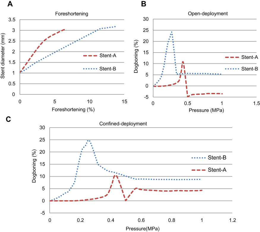 |
Figure 8 Quntitative relation of foreshortening (A), and dogboning (B) during open-deployment, and confined-deployment dogboning of stent-A (Cypher Bx Velocity) and stent-B (Savior Stent) (C). |
Dog-boning
Dog-boning is the difference between stent diameter at the extreme end and the diameter at proximity. Such a phenomenon is very common in angioplasty of a stent due to the uneven loading distribution hence uneven expansion along the length of the stent during deployment. Mathematically it can be expressed as follows:
(4)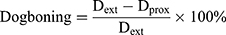
Where Dext is the diameter at extremities; and Dprox is the diameter at proximity of the stent. Figure 8B shows dog-boning against the pressure of inflation throughout the step for open-deployment. It is clear from graphical relations that the peak value of dog-boning occurs during the initial stage of pressure incrimination. The maximum value predicted at 0.44 MPa for stent-A was 11% and at 0.28 MPa for stent-B was 24%. Furthermore, stent-A gave negative dog-boning after retrieval from peak value expressing a barreled-shape structure. Moreover, the folded profile of the balloon has more impact on thinner struts compared to thicker struts geometry.
Elastic recoil
Radial elastic recoil is the difference between average diameter at the maximum pressure and diameter at zero pressure when the balloon is fully deflated. Almost every stent encounters two types of radial elastic recovery. A short-term recovery takes place immediately followed by the balloon deflation due to the material elastic property, while long-term recovery occurs in the following months of the treatment due to the constant compressive loading of vessel pulsation. Too much recovery leads to collapsing of the stent hence failure to serve the purpose. Both of these short- and long-term factors of stents are usually undesirable. It turns out that the elastic recoil along the stent length is not uniform, especially in cases of confined-deployment due to the high compressive load in the center of stent. Therefore it is measured at different locations such as at both extreme ends, at the center and average value along the stent length (longitudinal) Table 3. The short-term average elastic recoil in percentage during open-deployment was found to be 2.26% and 1.84% for stent-A, and B, respectively.
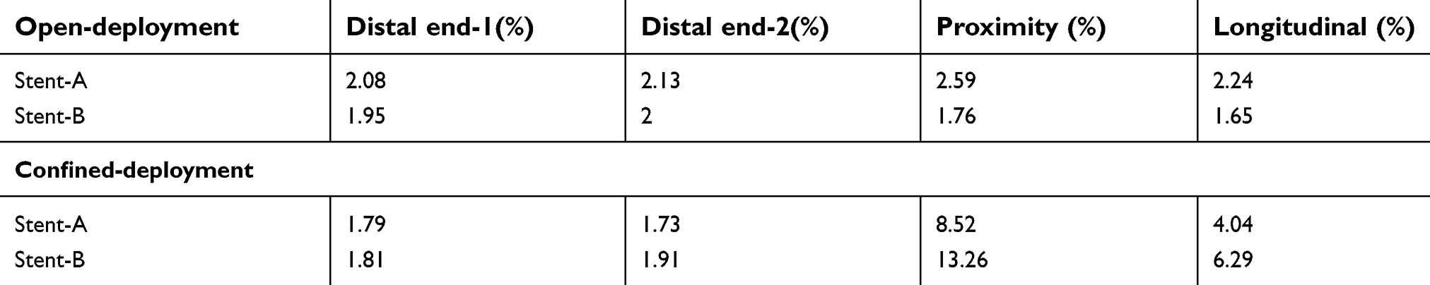 |
Table 3 Elastic radial recoil at the outer edges, at center and average value along the length of the stent for both configurations |
Confined-deployment
The artery configuration of both models is shown in Figure 9, at four different steps during confined-deployment. Figure 10 demonstrates a relationship between pressure and diameter for each stent. Compared with the open-deployment, it is clear that the artery has a less significant effect on the total inflation pressure. It can be seen that, for the same amount of pressure the curves lie a bit lower, this is due to the resistance of artery layers. The nominal diameter (3 mm) of stent reaches a higher pressure of 22% for stent-A and 22.6% for stent-B, compared to open-deployment.
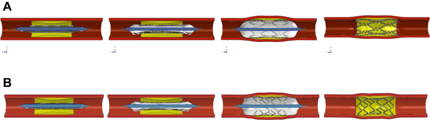 |
Figure 9 Expansion of confined-deployment configuration: stent-A (A) and stent-B (B). |
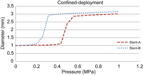 |
Figure 10 Pressure vs diameter plot for confined-deployment. |
Based on the above equation, the foreshortening documented was lower by 5.6% for stent-A and 37.46% for stent-B. Compared with open-deployment configuration, the lower value is because of the sliding resistance to the stent strut in the presence of artery plaque surface friction. In contrary to the open-deployment, the maximum dog-boning during confined-deployment was recorded when the balloon was fully deflated as shown in Figure 8C. This is due to the semi-elliptical shape of plaque, which causes high load concentration in the central region of the stent hence more radial recoil in the proximal diameter compared to the distal end diameter.
The value of dog-boning in confined-deployment was found to be 4.6% for stent-A and 4% for stent-B, higher than in open-deployment. The predicted elastic radial recoil was 43.8% for stent-A and 68.4% for stent-B, higher compared to open-deployment (Table 4). This also reveals that stent-A with thicker strut segments poses more resistance against artery recovery as compared to stent-B. Such a discrepancy between the two configurations was featured by artery radial recoil loading.
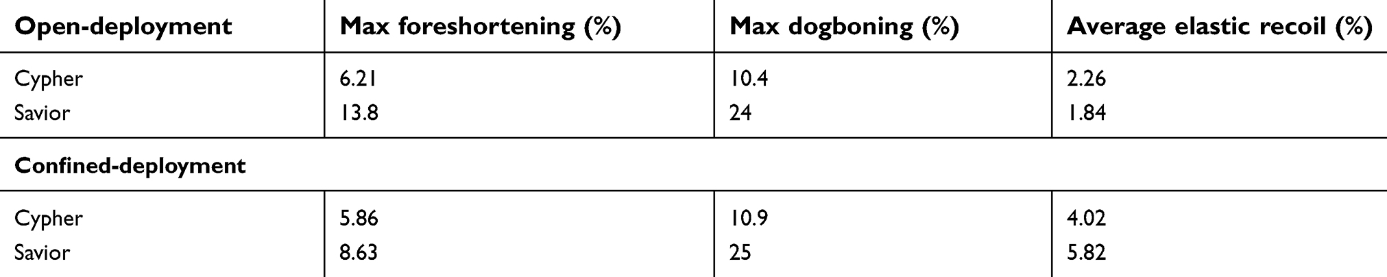 |
Table 4 Main parameters of interest resulted from computation analysis after the load removal for both stents at nominal diameter, during open and confined-deployment |
Figure 7B (above), shows the Von Mises stress distribution in both stents for confined configuration. It is interesting to note that the maximum intensity of stress was found in the crown of sinusoidal segments at the mid-section of the stent due to the plaque severity. The inclusion of artery also adds up to 15.4% higher peak stresses for stent-A and only 1% for stent-B, when compared to open-deployment.
Figure 11A shows the results equivalent induced stresses distribution due to stent-A geometries in different layers of artery. A maximum stress of 2.46 MPa, was found in the innermost layer such as plaque, while minimum stress of 0.057 MPa, was recorded in the outermost layer of artery such as adventitia. Stresses induced due to stent-B, in plaque by 38.5%, in intima by 32.6%, in media by 37.3%, and in adventitia by 38.6% had lower values compared to stent-A as depicted in Figure 11B. These outcomes lead to the conclusion that in spite of the thinner struts, the stent that remained intact with the artery through a small interaction area, and the large elastic recoil in stent-A during confined-deployment results in smaller stress induction in artery layers as well as minor increment in stent peak stresses compared to stent-B as mentioned above in Table 5.
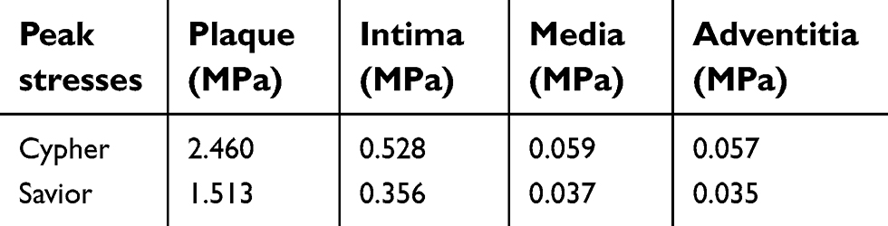 |
Table 5 Maximum stresses found in individual layers of artery due to stent-A and stent-B |
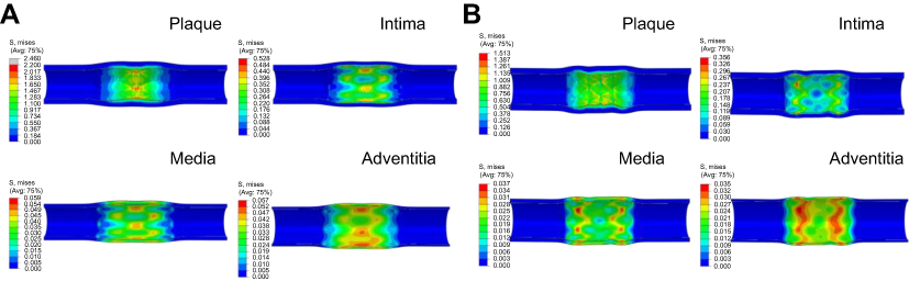 |
Figure 11 von Mises stress destribution in different layers of artery due to stent implantation: stent-A (A), stent-B (B). |
Limitations
There were a number of assumptions made during the solution setup. These included the geometries of the Stents and the balloon itself. The stent models were sketched and imported based on documented dimensions rather than using micro-CT images technique. However, such assumptions should not have a major impact especially in the case of a comparison study. The exclusion of hemodynamics effect such as the flow of blood and damping can cause a slight diversity in the solutions. Nevertheless, such limitations were compensated by defining the damping factor for balloon membrane material (Abaqus documentation).
Although an idealized elastic model was used for balloon material, the folded configuration accompanied with catheter-shaft attachment leads to a good agreement of pressure-diameter relation with compliance data. The complex mechanical properties of human tissues, idealized using isotropic and homogenous constitutive material model for artery and plaque is the major obstacle with any numerical analysis. Nevertheless, the Ogden model has proved to be the most powerful to mimic the mechanical response of hyper-elastic material such as human blood vessels.
The use of a mass-scaling technique was adopted from online Abaqus documentation 6.14. This tactic slightly deviated the final results, especially for stresses distribution. However, a separate set of static analysis (Abaqus/Standard) was also carried out using an analytical surface as a cylindrical balloon for the same amount of stent deformation, triggered by displacement-driven boundary condition. The subsequent stresses which originated, were less than 1% different to that of the results from Abaqus/explicit solution in the presence of semi-automated mass scaling.
Conclusion
In this study, the deployment of two different stent models was simulated under the inflation of a sophisticated balloon configuration considering the impact of guide wire and catheter-shaft effectively connected together. The confined-deployment of the stents under the influence of different artery layers, takes the numerical investigation of stent angioplasty one step further. In this investigation, the first assessment was made for a newly commercialized Savior Stent to compare with a well-known and well-documented Cypher Bx_Velocity stent to comprehend the clinical efficiency. The comparison was based on certain design parameters such as pressure expansion, foreshortening, dog-boning, elastic recoil and the distribution of maximum stresses. These parameters play a significant role in the stent-restenosis, flexibility, good deliverability, and life time sustainability. Stent-A, proved to be more persistent to trail the lesion profile showing high rigidity, more resistance to radial recovery, retaining a good deal of lumen shape, with adequate stresses generation, hence good durability. On the other hand, a thinner strut stent design such as stent-B, means less foreign material, access to more complex stenosed regions, ease of expansion, high flexibility, and extraordinary deliverability. Such design parameters are desirable and efforts are being made to improve. This shows that, there must always be a right balance between these criteria to acquire a better qualitative design. Secondly the connections between the sinusoidal segments through different shape of linkages have a significant influence on the stent's overall performance. For instance, the N-shaped head-to-head connection (stent-A) allows a slight extension in the longitudinal direction hence reducing the occurrence of foreshortening. Whereas the cross-linkage configuration (stent-B), reduces the stresses in the circumferential direction (hoop stress σθ) and is equally as resistant to collapsing. The elastic recoil in stent-B was much higher compared to stent-A. Consequently, the stresses induced in the artery layers were relatively low. Similarly, the percentage of increment in stent peak stresses during confined-deployment was lower due to the same reason.
Although it is too early for any highly conclusive evidence, it is still recommended that the head-to-head crown joining of stent-A, should be adopted for any new emerging design. This provides more controlled expansion and prevents the slipping forward of the curved crown, as observed in the stent-B design. Because its absence gives rise to high prolapse in plaque material and hence contact stresses this increases the chances of injuries. Secondly, if the bridge connection linkage accompanied with wave-shape design such as N-shape in stent-A, it can significantly reduce the phenomenon of foreshortening. Moreover, for future study in the computational mechanics and its validation (study of global behavior), the folded pattern of balloon and its attachment to the catheter-shaft should be taken into greater consideration while using Abaqus/Explicit method. However, for stress analysis alone (study of local behavior), the folded configuration can be ignored to reduce the computational time. It is more appropriate to use Abaqus/Stand simulation method for such investigation particularly in the design of new generation stents. This not only significantly reduces the computational time but also eliminates the occurrence of inertial effects.
Disclosure
The authors report no conflicts of interest in this work.
References
1. Lloyd-Jones D. Heart disease and stroke statistics–2009 update: a report from the American Heart Association Statistics Committee and Stroke Statistics Subcommittee. Circulation. 2009;119(3):E182–E182.
2. Murray SW, Cooper RM, Appleby C, et al. Double jeopardy: multi-modality imaging of monozygotic “twin cap” atherosclerosis. Atherosclerosis. 2014;237(1):264–267. doi:10.1016/j.atherosclerosis.2014.09.018
3. Frohlich J, Dobiasova M, Lear S, Lee KW. The role of risk factors in the development of atherosclerosis. Crit Rev Clin Lab Sci. 2001;38(5):401–440. doi:10.1080/20014091084245
4. De Beule M. Chapter 2 - Biomechanical modeling of Stents: Survey 1997–2007. In: Verdonck P, editor. Advances in Biomedical Engineering. Amsterdam: Elsevier Science; 2009:61–94.
5. Brauer H, Stolpmann J, Hallmann H, Erbel R, Fischer A. Measurement and numerical simulation of the dilatation behaviour of coronary stents. Materialwiss Werkst. 1999;30(12):876–885. doi:10.1002/(SICI)1521-4052(199912)30:12<876::AID-MAWE876>3.0.CO;2-O
6. Argente Dos Santos HA, Auricchio F, Conti M. Fatigue life assessment of cardiovascular balloon-expandable stents: a two-scale plasticity-damage model approach. J Mech Behav Biomed Mater. 2012;15(78–92). doi:10.1016/j.jmbbm.2012.06.011
7. Grossman’s Cardiac Catheterization, Angiography and Intervention, 6th ed. Baim DS, editor. Philadelphia: Lippincott Williams & Wilkins; 2000.
8. Farb A, Sangiorgi G, Carter AJ, et al. Pathology of acute and chronic coronary stenting in humans. Circulation. 1999;99(1):44–52.
9. Rosamond W, Flegal K, Friday G, et al. Heart disease and stroke statistics–2007 update: a report from the American Heart Association Statistics Committee and Stroke Statistics Subcommittee. Circulation. 2007;115(5):e169–171. doi:10.1161/CIRCULATIONAHA.106.179918
10. Gervaso F, Capelli C, Petrini L, Lattanzio S, Di Virgilio L, Migliavacca F. On the effects of different strategies in modelling balloon-expandable stenting by means of finite element method. J Biomech. 2008;41(6):1206–1212. doi:10.1016/j.jbiomech.2008.01.027
11. Dumoulin C, Cochelin B. Mechanical behaviour modelling of balloon-expandable stents. J Biomech. 2000;33(11):1461–1470.
12. Etave F, Finet G, Boivin M, Boyer JC, Rioufol G, Thollet G. Mechanical properties of coronary stents determined by using finite element analysis. J Biomech. 2001;34(8):1065–1075.
13. Migliavacca F, Petrini L, Colombo M, Auricchio F, Pietrabissa R. Mechanical behavior of coronary stents investigated through the finite element method. J Biomech. 2002;35(6):803–811.
14. Chua SND, Mac Donald BJ, Hashmi MSJ. Finite element simulation of stent and balloon interaction. J Mater Process Tech. 2003;143:591–597. doi:10.1016/S0924-0136(03)00435-7
15. Petrini L, Migliavacca F, Auricchio F, Dubini G. Numerical investigation of the intravascular coronary stent flexibility. J Biomech. 2004;37(4):495–501. doi:10.1016/j.jbiomech.2003.09.002
16. Migliavacca F, Petrini L, Montanari V, Quagliana I, Auricchio F, Dubini G. A predictive study of the mechanical behaviour of coronary stents by computer modelling. Med Eng Phys. 2005;27(1):13–18. doi:10.1016/j.medengphy.2004.08.012
17. Hall GJ, Kasper EP. Comparison of element technologies for modeling stent expansion. J Biomech Eng-T Asme. 2006;128(5):751–756. doi:10.1115/1.2264382
18. Wang WQ, Liang DK, Yang DZ, Qi M. Analysis of the transient expansion behavior and design optimization of coronary stents by finite element method. J Biomech. 2006;39(1):21–32. doi:10.1016/j.jbiomech.2004.11.003
19. De Beule M, Mortier P, Carlier SG, Verhegghe B, Van Impe R, Verdonck P. Realistic finite element-based stent design: the impact of balloon folding. J Biomech. 2008;41(2):383–389. doi:10.1016/j.jbiomech.2007.08.014
20. Lim DY, Cho SK, Park WP, et al. Suggestion of potential stent design parameters to reduce restenosis risk driven by foreshortening or dogboning due to non-uniform balloon-stent expansion. Ann Biomed Eng. 2008;36(7):1118–1129. doi:10.1007/s10439-008-9504-1
21. Jovicic GR, Vukicevic AM, Filipovic ND. Computational assessment of stent durability using fatigue to fracture approach. J Med Devices. 2014;8:4. doi:10.1115/1.4027687
22. Chua SND, MacDonald BJ, Hashmi MSJ. Finite element simulation of slotted tube (stent) with the presence of plaque and artery by balloon expansion. J Mater Process Tech. 2004;155:1772–1779. doi:10.1016/j.jmatprotec.2004.04.396
23. Lally C, Dolan F, Prendergast PJ. Cardiovascular stent design and vessel stresses: a finite element analysis. J Biomech. 2005;38(8):1574–1581. doi:10.1016/j.jbiomech.2004.07.022
24. Liang DK, Yang DZ, Qi M, Wang WQ. Finite element analysis of the implantation of a balloon-expandable stent in a stenosed artery. Int J Cardiol. 2005;104(3):314–318. doi:10.1016/j.ijcard.2004.12.033
25. Holzapfel G, Stadler M, Gasser TC. Changes in the mechanical environment of stenotic arteries during interaction with stents: computational assessment of parametric stent designs. J Biomech Eng-T Asme. 2005;127(1):166–180. doi:10.1115/1.1835362
26. Bedoya J, Meyer CA, Timmins LH, Moreno MR, Moore JE. Effects of stent design parameters on normal artery wall mechanics. J Biomech Eng-T Asme. 2006;128(5):757–765. doi:10.1115/1.2246236
27. Gijsen FJ, Migliavacca F, Schievano S, et al. Simulation of stent deployment in a realistic human coronary artery. Biomed Eng Online. 2008;7:23. doi: 10.1186/1475-925X-7-23
28. Capelli C, Gervaso F, Petrini L, Dubini G, Migliavacca F. Assessment of tissue prolapse after balloon-expandable stenting: influence of stent cell geometry. Med Eng Phys. 2009;31(4):441–447. doi:10.1016/j.medengphy.2008.11.002
29. Pericevic I, Lally C, Toner D, Kelly DJ. The influence of plaque composition on underlying arterial wall stress during stent expansion: the case for lesion-specific stents. Med Eng Phys. 2009;31(4):428–433. doi:10.1016/j.medengphy.2008.11.005
30. Martin D, Boyle F. Finite element analysis of balloon-expandable coronary stent deployment: influence of angioplasty balloon configuration. Int J Numer Method Biomed Eng. 2013;29(11):1161–1175. doi:10.1002/cnm.2557
31. Mortier P, Hikichi Y, Foin N, et al. Provisional stenting of coronary bifurcations insights into final kissing balloon post-dilation and stent design by computational modeling. JACC-Cardiovasc Inte. 2014;7(3):325–333. doi:10.1016/j.jcin.2013.09.012
32. Zhao SJ, Gu LX. Computational framework for modeling in-stent restenosis. J Med Devices. 2014;8:2. doi:10.1115/1.4027062
33. Holzapfel GA, Stadler M, Schulze-Bauer CAJ. A layer-specific three-dimensional model for the simulation of balloon angioplasty using magnetic resonance imaging and mechanical testing. Ann Biomed Eng. 2002;30(6):753–767.
34. Kastrati A, Mehilli J, Dirschinger J, et al. Intracoronary stenting and angiographic results. Circulation. 2001;103:2816–2821.
35. Holzapfel GA, Sommer G, Gasser CT, Regitnig P. Determination of layer-specific mechanical properties of human coronary arteries with nonatherosclerotic intimal thickening and related constitutive modeling. Am J Physiol Heart Circulatory Physiol. 2005;289(5):H2048–H2058. doi:10.1152/ajpheart.00934.2004
36. Poncin P, Proft J. Stent tubing: understanding the desired attributes. Presentation at: Materials & Process for Medical Devices Conference; September 8–10, 2003; Anaheim, CA, USA.
37. Kim B, Lee SB, Lee J, et al. A comparison among Neo-Hookean model, Mooney-Rivlin model, and Ogden model for chloroprene rubber. Int J Precis Eng Manuf. 2012;13(5):759–764. doi:10.1007/s12541-012-0099-y
38. Loree HM, Grodzinsky AJ, Park SY, Gibson LJ, Lee RT. Static circumferential tangential modulus of human atherosclerotic tissue. J Biomech. 1994;27(2):195–204.
39. ABAQUS (2010) Analysis User’s Manual. Version 6.10. Providence: Dassault Systemes Simulia, Inc.; 2010.
 © 2019 The Author(s). This work is published and licensed by Dove Medical Press Limited. The full terms of this license are available at https://www.dovepress.com/terms.php and incorporate the Creative Commons Attribution - Non Commercial (unported, v3.0) License.
By accessing the work you hereby accept the Terms. Non-commercial uses of the work are permitted without any further permission from Dove Medical Press Limited, provided the work is properly attributed. For permission for commercial use of this work, please see paragraphs 4.2 and 5 of our Terms.
© 2019 The Author(s). This work is published and licensed by Dove Medical Press Limited. The full terms of this license are available at https://www.dovepress.com/terms.php and incorporate the Creative Commons Attribution - Non Commercial (unported, v3.0) License.
By accessing the work you hereby accept the Terms. Non-commercial uses of the work are permitted without any further permission from Dove Medical Press Limited, provided the work is properly attributed. For permission for commercial use of this work, please see paragraphs 4.2 and 5 of our Terms.