")
Back to Journals » International Journal of Nanomedicine » Volume 10 » Issue 1
Association of electrospinning with electrospraying: a strategy to produce 3D scaffolds with incorporated stem cells for use in tissue engineering
Authors Braghirolli D, Zamboni F, Acasigua GAX, Pranke P
Received 10 March 2015
Accepted for publication 26 May 2015
Published 14 August 2015 Volume 2015:10(1) Pages 5159—5170
DOI https://doi.org/10.2147/IJN.S84312
Checked for plagiarism Yes
Review by Single anonymous peer review
Peer reviewer comments 6
Editor who approved publication: Dr Thomas Webster
Daikelly Iglesias Braghirolli,1,2 Fernanda Zamboni,1 Gerson AX Acasigua,1,3 Patricia Pranke1,2,4
1Hematology and Stem Cells Laboratory, Faculty of Pharmacy, 2Department of Materials Science, 3School of Dentistry, Universidade Federal do Rio Grande do Sul, Porto Alegre, Rio Grande do Sul, Brazil; 4Instituto de Pesquisas com Células-Tronco, Porto Alegre, Rio Grande do Sul, Brazil
Abstract: In tissue engineering, a uniform cell occupation of scaffolds is crucial to ensure the success of tissue regeneration. However, this point remains an unsolved problem in 3D scaffolds. In this study, a direct method to integrate cells into fiber scaffolds was investigated by combining the methods of electrospinning of fibers and bioelectrospraying of cells. With the associating of these methods, the cells were incorporated into the 3D scaffolds while the fibers were being produced. The scaffolds containing cells (SCCs) were produced using 20% poly(lactide-co-glycolide) solution for electrospinning and mesenchymal stem cells from deciduous teeth as a suspension for bioelectrospraying. After their production, the SCCs were cultivated for 15 days at 37°C with an atmosphere of 5% CO2. The 3-(4,5-dimethylthiazol-2-yl)-2,5-diphenyltetrazolium bromide test demonstrated that the cells remained viable and were able to grow between the fibers. Scanning electron microscopy showed the presence of a high number of cells in the structure of the scaffolds and confocal images demonstrated that the cells were able to adapt and spread between the fibers. Histological analysis of the SCCs after 1 day of cultivation showed that the cells were uniformly distributed throughout the thickness of the scaffolds. Some physicochemical properties of the scaffolds were also investigated. SCCs exhibited good mechanical properties, compatible with their handling and further implantation. The results obtained in the present study suggest that the association of electrospinning and bioelectrospraying provides an interesting tool for forming 3D cell-integrated scaffolds, making it a viable alternative for use in tissue engineering.
Keywords: bioelectrospraying, cell speed, mesenchymal stem cells, tissue engineering, 3D scaffolds
Introduction
Electrospinning is an easy and cost-effective method to produce scaffolds, largely used in tissue engineering. The electrospun scaffolds are formed by fibers that are able to mimic in structure and scale the collagen fibers of the native extracellular matrix, providing a favorable and biomimetic microenvironment for cell adhesion, spreading, and development.1,2
The efficacy of the use of scaffolds depends on their capacity to interact with cells. The interaction between the cells and scaffolds begins with the seeding process. In this stage, the isolated cells are disseminated into or onto the scaffolds prior to their in vitro culture or in vivo implantation. Cell seeding is a crucial step for establishing a 3D culture and to guarantee the success of tissue engineering. Its purpose is to ensure a uniform cellular colonization in the scaffold structure to promote a fast and homogeneous new tissue formation.3,4
Various methods are used to seed cells on scaffolds. Static seeding is the most common method to associate the cells with the scaffolds. It consists of spreading a known concentration of cells onto the scaffold surface with a micropipette and it can be applied for different types of scaffolds. However, this technique presents certain disadvantages, such as low seeding efficiency, no uniform distribution of the cells in the 3D structure of the material, and poor cell infiltration in all its grades of thickness.4–6 In electrospun scaffolds, the permeation of cells between their fibers can be yet more complex. Using specific parameters, electrospinning can exhibit a tendency to accumulate densely packed fibers. In these cases, the resulting scaffolds can exhibit relatively small-sized pores in comparison with the cell diameter.7,8 These characteristics can lead to development of cells only on the surface of the scaffold, resulting in a bidimensional system culture. Because of this, other methods are being proposed to optimize cellular seeding in electrospun fibers.
Bioelectrospraying is a technology in which a suspension of living cells is passed through a charged needle, generating droplets containing cells.5,9 The association between bioelectrospraying and electrospinning techniques is a promising alternative to produce scaffolds containing cells (SCCs). The combination of these two methods promotes the direct integration of living cells during the scaffold production. Therefore, the cells are homogeneously distributed between the fibers of electrospun scaffolds, favoring the creation of a real 3D system to be applied to tissue engineering.10,11
Mesenchymal stem cells (MSCs) are multipotent stem cells with great plasticity, which secrete different bioactive factors that can assist in the regeneration process at the tissue injury site.12,13 In a previous study,14 our group demonstrated that MSCs can be safely electrosprayed, subject to compliance of the applied voltage and time of electrospraying processing.
After a review of the current literature, we verified that there are few studies concerning the association of electrospinning and electrospraying techniques to produce SCCs. Yet, despite the great potential of the application of stem cells in tissue engineering, none of the studies have evaluated the direct integration of MSCs into fibers during scaffold production. Furthermore, the studies carried out to date do not evaluate the efficiency of this direct seeding process. They have also not investigated the effects of direct integration of the cells on the physicochemical properties of the fibers.
Therefore, the aim of this work was to investigate the association of the bioelectrospraying and electrospinning techniques to produce scaffolds with stem cells incorporated into their structures. The efficiency of the integration of the cells into the electrospun scaffolds and the physicochemical and biological properties of the produced scaffolds were evaluated.
Materials and methods
Culture of MSCs and preparation of cell suspension
MSCs were isolated from human deciduous teeth pulp (n=5) and characterized, as described by Bernardi et al15 after approval by the Ethics Committee of the Federal University of Rio Grande do Sul.
The cells were cultivated in Dulbecco’s Modified Eagle’s Medium (DMEM) containing 2.5 g/L 4-(2-hydroxyethyl)-1-piperazineethanesulfonic acid (HEPES; free acid) (Sigma-Aldrich Co., St Louis, MO, USA) supplemented with 10% bovine fetal serum (Thermo Fisher Scientific, Waltham, MA, USA), 100 U/mL penicillin, 100 μg/mL streptomycin (Thermo Fisher Scientific), and 0.45 μg/mL gentamicin and maintained in a humid atmosphere of 5% CO2, at 37°C. The culture medium was changed every 3 days or 4 days. When they had reached 90% confluence at the fifth passage, the cells were detached with 0.5% trypsin–ethylenediaminetetra acetic acid solution (Sigma-Aldrich Co.) and resuspended in culture medium. Cellular suspensions with concentrations from 3×10⁶ cells/mL to 7.5×10⁶ cells/mL were subjected to bioelectrospraying.
Polymeric solution preparation
The scaffolds were produced using poly(lactide-co-glycolide) (PLGA) 75:25 (Sigma-Aldrich Co.). The polymer was dissolved in 1,1,1,3,3,3-hexafluoro-2-propanol (HFIP) (Sigma-Aldrich Co.) such that the final concentration was 20% (w/v). Following this, the solution was maintained overnight in magnetic agitation for complete homogenization.
Production of the SCCs
To integrate the cells into the fiber scaffolds, the electrospinning and bioelectrospraying techniques were applied in association. For the combination of the two methods, an apparatus formed by two parallel infusion systems (Figure 1) was used. The polymer solution was electrospun at 0.54 mL/h flow rate under 15 kV at a distance of 7.5 cm from the needle (inner diameter: 0.6 mm) to the collector plate. The cell suspensions were electrosprayed at a flow rate of 2.60 mL/h, distance of 4 cm, and voltage of 15 kV. The SCCs were formed on a Petri dish placed on a horizontal rotating plate collector (60 rpm). After 15 minutes of polymer electrospinning and electrospraying of the cells, the formed SCCs were covered with DMEM and incubated at 37°C in a 5% CO2 atmosphere. For physicochemical analysis, control scaffolds (CSs) were produced. The CS group was produced using the same electrospinning parameters used for the production of SCCs (0.54 mL/h, 15 kV, 7.5 cm) but without its association with bioelectrospraying.
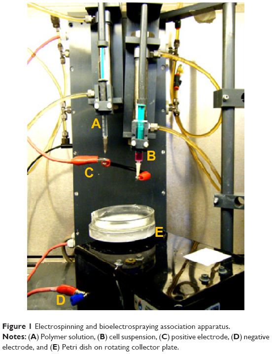 | Figure 1 Electrospinning and bioelectrospraying association apparatus. |
Physicochemical characterization of SCCs
For the physicochemical analysis, the SCCs were washed immediately after their production with phosphate-buffered saline (PBS) to remove the cells. The washes were repeated many times. Following this, the samples were dried at 30°C for 24 hours.
Fiber morphology, fiber diameter, and scaffold dimensions
The morphology of SCCs and CSs was analyzed by scanning electron microscopy (SEM) (JEOL JSM-6060) with accelerating voltage of 10 kV after coating with a thin layer of gold (about 15 nm) using a sputter coater (Bal-Tec SCD 050). The average diameter of the fibers was determined from the SEM micrographs using ImageJ 1.38× software by measuring 30 fibers from each image (n=3). The thickness of the scaffolds was measured using a micrometer (Digimatic Micrometer MDC-25MY; Mitutoyo).
In vitro degradation
The SCCs and CSs were incubated in PBS at 37°C, under 100 rpm agitation and at pH 7.4. The samples were collected at different intervals (0 day, 1 day, 7 days, 15 days, 30 days, and 45 days), washed repeatedly with distilled water, and dried at 30°C. The changes in the average molecular weight (Mw) of the samples were estimated by gel permeation chromatography (Viscotek VE 2001) module equipped with a refraction index detector. The scaffolds were dissolved in tetrahydrofuran and eluted at a flow rate of 1 mL/min at 45°C. The polystyrene standard was used to obtain the first calibration curve.
Mechanical properties
Young’s modulus, maximum load, and maximum elongation of the SCCs and the CSs were determined by dynamic mechanical analysis (DMA) (n=5) (Q800AT DMA instrument equipped with a tension film clamp in the DMA controlled force mode). The scaffolds were cut into rectangular shapes (5×12 mm). The assays were carried out at constant temperature (37°C) with ramp force of 0.5 N/min until 18 N maximum load, under 0.005 N static load.
Residual solvent
The residual solvent content was evaluated in the CS group (n=3) by thermogravimetric analysis (TGA) (SDTQ600 simultaneous TGA/differential scanning calorimeters) in a nitrogen atmosphere. About 10–12 mg scaffold samples were held at 25°C for 5 minutes, followed by heating at a rate of 20°C/min (from 25°C to 750°C) and then heating at 70°C/min until 800°C.
Biological properties of SCCs
For all biological analyses, the SCCs were incubated at 37°C and 5% CO2, as done immediately after production. One exception was the analysis of cell viability. For this assay, the SCCs were washed with PBS after being produced, as described below.
Cell viability in the SCCs
For evaluation of cell viability after the electrospinning and electrospraying processes, the SCCs were washed with PBS after being produced. The wash buffer containing the cells removed from the scaffolds was centrifuged, and the pellet was resuspended in a known volume of PBS. The viability of the electrosprayed cells was determined by counting in a Neubauer chamber with 0.4% trypan blue (triplicate, n=3).
As a control of the process, the bioelectrospraying was performed without its association with fiber electrospinning. The cells were electrosprayed into a Petri dish containing the culture medium, using the same decrypted parameters (flow rate of 2.60 mL/h, distance of 4 cm, and applied voltage of 15 kV for 15 minutes). Following this, the medium was centrifuged and the cells were counted in a Neubauer chamber with trypan blue (n=3).
Initial cell number and cell proliferation in SCCs
After their production, the SCCs were incubated for 4 hours at 37°C and 5% CO2. After this period, SCC fragments of 1 cm2 area were cut and placed in 24-well plates. The number of integrated cells in the scaffold structure was obtained by a colorimetric method using 3-(4,5-dimethylthiazol-2-yl)-2,5-diphenyltetrazolium bromide (MTT) and a standard MTT absorbance curve for MSCs of a known concentration. For this assay, the samples were incubated with 0.25 μg/mL MTT in calcium and magnesium free buffer for 2 hours at 37°C. The MTT solution was then removed, and the formed crystals were solubilized in 400 μL of dimethyl sulfoxide (DMSO). The absorbance of the DMSO containing soluble formazan blue was read at 560 nm, with 630 nm as reference (Wallac EnVision; PerkinElmer).
The efficiency of integration of cells into SCCs by the association of electrospinning and bioelectrospraying was calculated using the initial viable cell density in the SCCs (as estimated by the MTT test), the worn volume of cell suspension during the bioelectrospraying, and the volume of the produced SCCs (about 270 mm3). Cell metabolism/proliferation in the SCCs was evaluated for 15 days. SCC sections (1 cm2) were cut at Days 1, 7, and 15 and analyzed by the MTT test (triplicate, n=3).
Cell distribution and morphology in SCCs
The integration and distribution of the cells in the SCCs were observed by SEM. Immediately after their production and after 1 day, 7 days, and 15 days of cultivation, the SCC samples were washed with PBS, fixed with 3% glutaraldehyde, and subjected to graded ethanol dehydrations before being coated with gold and imaged. The cellular morphology was observed by confocal microscopy (Olympus SV1000; ×40 lens). After 1 day, 7 days, and 15 days of cultivation, the SCC samples were washed with PBS, fixed with 4% paraformaldehyde, permeabilized with 0.1% Triton X-100, and stained with 50 μg/mL rhodamine phalloidin (40 minutes) for actin and 0.5 μg/mL 4,6-diamidino-2-phenylindole (1 minute) for nuclei.
Histological analysis
The cell distribution in all grades of thicknesses of the SCCs was evaluated by histological analysis after 1 day and 15 days of cultivation. The SCCs were fixed with 4% paraformaldehyde, dehydrated in serial solutions of ethanol (60%–100%), and embedded in paraffin, as described by Paletta et al.11 SCC cross-sections (5-μm thickness) were stained with hematoxylin and eosin and analyzed using a combination of an optical microscope, a video camera (Olympus® Q-Color 5™, Cooler, real-time viewing mode), and a computer (Dell® Dimension 5150) using Qcapture® software (2.81 version; Quantitative Imaging Corporation, Inc, 2005).
Statistical analysis
The results were analyzed and are presented as means ± standard deviations and the symmetry study of the distributions was performed using the Shapiro–Wilk test. Comparison of the groups was made with a one-way analysis of variance, followed by the Tukey’s test. The fiber diameter, thickness of the scaffolds, and degradation of the SCCs and the CSs were compared using the Mann–Whitney test. Mechanical properties of the groups were compared using the t-test. Differences were considered significant when P<0.05.
Results
SCC production
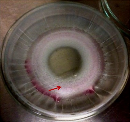
SCCs were produced by the association of the bioelectrospraying and electrospinning methods (Figure 2). Cellular suspensions with concentrations ranging from 3×10⁶ cells/mL to 7.5×10⁶ cells/mL could be electrosprayed successfully without the need for changes in the bioelectrospraying parameters. The suspension with concentration 7.5×10⁶ cells/mL was chosen for SCC production. During SCC formation, it was observed that the direction of the electrospraying jet was in a central position in the fiber area formed by electrospinning. Because of this, the electrospraying bomb was rotated every 5 minutes to increase the bioelectrospraying and electrospinning convergence area, creating a more homogeneous cellular distribution among the electrospun fibers. After production of SCCs, their physicochemical and biological properties were evaluated.
 | Figure 2 Sample of scaffold containing cells after production. |
Physicochemical properties
Fiber morphology, fiber diameter, and thickness of the scaffolds
From the images obtained by SEM, it can be observed that the fibers in SCCs and CSs exhibited a smooth surface and were distributed randomly over the entire scaffold structure (Figure 3A and B). The fibers showed an average diameter of 3.5±6.1 μm in the SCCs and 1.5±2.2 μm in the CSs (P<0.001). The SCCs were also significantly (129.4±47.5 μm) thicker than the CSs (56.6±13.3 μm) (P=0.016).
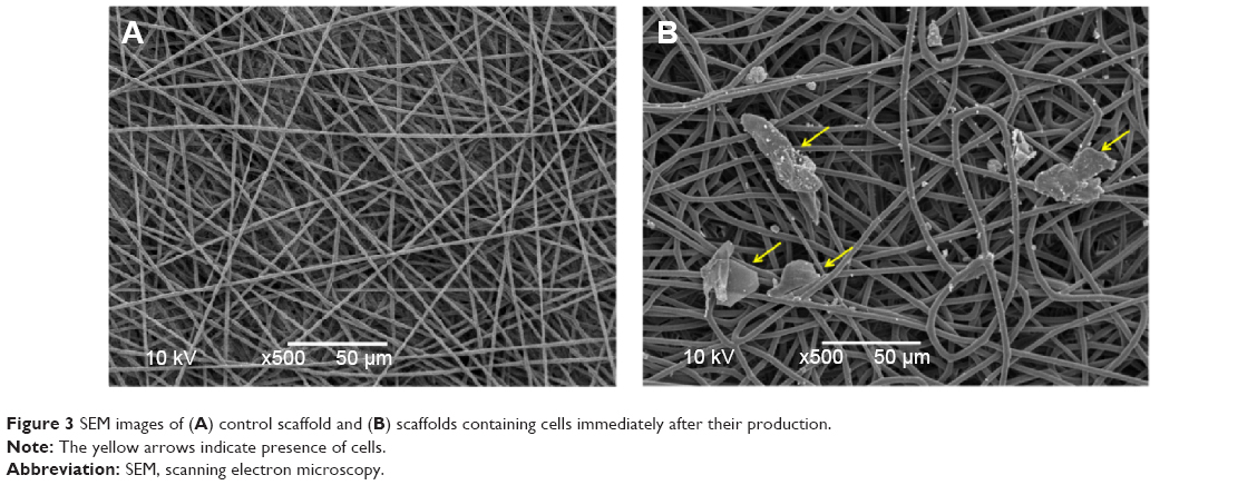 | Figure 3 SEM images of (A) control scaffold and (B) scaffolds containing cells immediately after their production. |
Degradation
The in vitro degradation of the SCCs and the CSs was evaluated for 45 days. The Mw of the CS group decreased more rapidly during the first 15 days. Meanwhile, the SCC group showed a greater Mw reduction between the 15th and 45th days (Figure 4). Although these differences were observed during the degradation interval, the final Mw was similar for the SSCs and the CSs, and there was no significant statistical difference between the groups. The Mw decreased about 39% and 32% for the SCCs and CSs, respectively, over a period of 45 days.
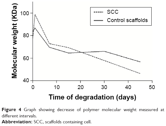 | Figure 4 Graph showing decrease of polymer molecular weight measured at different intervals. |
Residual solvent content
In TGA analysis, mass loss at temperatures <200°C normally indicates the volatilization of organic solvents or water. The CSs exhibited a 2.88% mass loss during the period in which they were exposed to this temperature. From this measurement, it can be supposed that 0.33±0.8 mg of solvent and/or humidity was present in the CSs.
Mechanical properties
Young’s modulus, maximum load, and maximum elongation of the scaffolds are presented in Figure 5A–C, respectively. The values of the measured mechanical properties were greater in the CSs than in the SCCs. It was observed that SCCs exhibited a greater variation in the mechanical property values than the CSs. The SCCs exhibited two types of tension-straining behavior. As can be seen in the graph of mechanical profile (Figure 6), the SCC group exhibited two ranges of average values for Young’s modulus and maximum load parameters. A representative sample of CSs was used to demonstrate the mechanical behavior of this group.
 | Figure 5 Mechanical properties of CSs and SCCs. |
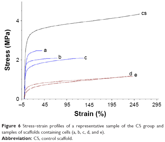 | Figure 6 Stress–strain profiles of a representative sample of the CS group and samples of scaffolds containing cells (a, b, c, d, and e). |
Biological properties
Viability of MSCs in SCCs and efficiency of the association of bioelectrospraying and electrospinning
Cell viability after bioelectrospraying (without its association with fiber electrospinning) was 93%±4.4%. Meanwhile, cell viability after the bioelectrospraying and electrospinning procedures was 89%±4.6%. The initial density of viable MSCs in the SCC structure was estimated using the MTT test by comparison of the absorbance of the sample with that of the standard (Figure 7). The average number of viable cells integrated between the fibers was (5.039±1.008)×103 cells/mm3.
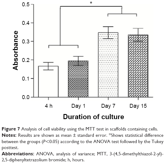 | Figure 7 Analysis of cell viability using the MTT test in scaffolds containing cells. |
The total volume of the SCCs was approximately 270 mm3. Thus, after production, the number of cells in the total volume of SCCs was approximately 1.36×10⁶. As previously mentioned, for the bioelectrospraying process, a 2.60 mL/h flow rate and an MSC suspension with 7.5×10⁶ cells/mL concentration was used. Thus, 0.65 mL of the cell suspension was used to produce each SCC, which corresponds to approximately 4.88×10⁶ cells.
By comparing the number of cells used for bioelectrospraying and the number of cells present in the SCC, the efficiency of cell integration achieved by the bioelectrospraying and electrospinning association was estimated. The calculated efficiency of cell integration by this combined technique was about 28%.
The metabolism/proliferation of the MSCs in the SCCs is shown in Figure 7. The number of viable cells increased significantly between the 1st and 7th days of cultivation (P<0.001). Meanwhile, between the 7th and 15th days, the MTT assay showed that the number of viable cells was maintained constant.
Distribution and morphology of MSCs in SCCs
The SEM micrographs of the SCCs immediately after their production show that the MSCs have a rounded morphology; few adhesion points on the fibers were observed. This analysis suggests that at this time, the cells still did not have strong adhesion with the scaffolds (Figure 8A). However, after 1 day of cultivation, the MSCs showed several contact points of adherence to the biomaterial, forming bridges between adjacent fibers. It was possible to observe cells above and below the fiber network (Figure 8B). After 7 days and 15 days of cultivation, higher numbers of cells were present in the structure of the scaffolds (Figure 8C and D).
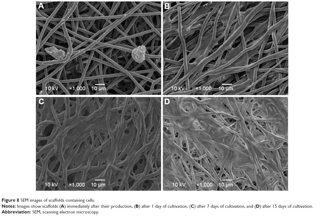 | Figure 8 SEM images of scaffolds containing cells. |
Confocal images demonstrated that the cells still showed a rounded morphology after 1 day of cultivation (Figure 9A). However, after 7 days and 15 days of cultivation, they exhibited a well-spread morphology (Figure 9B and C). On the 15th day, greater numbers of cells in the first layers of SSCs were observed.
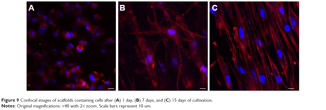 | Figure 9 Confocal images of scaffolds containing cells after (A) 1 day, (B) 7 days, and (C) 15 days of cultivation. |
Cross-sections of paraffin-embedded SCCs after 1 day of cultivation showed that the MSCs were uniformly distributed throughout the thickness of the scaffolds (Figure 10A). The images from the middle and from the right and left ends of the SCCs prove that a pronounced integration of cells occurred in the central portion of the SCCs. In the middle of the scaffolds, a larger number of cells could be visualized, while in the outermost portions, lesser number of cells was found. However, after 15 days of cultivation, the cross-sections of the SCCs demonstrated an increase in the number of cells and an improved filling of the scaffold structure by the MSCs (Figure 10B). The cells were able to proliferate and fill the ends of the SSCs. No difference was observed between the different portions of the scaffolds.
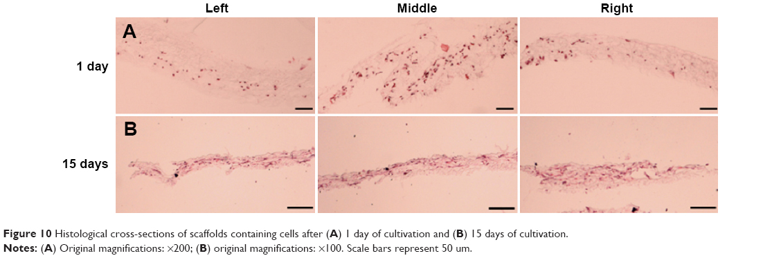 | Figure 10 Histological cross-sections of scaffolds containing cells after (A) 1 day of cultivation and (B) 15 days of cultivation. |
Discussion
Uniform spatial occupation of cells in the scaffold structure is very important for the development of the regenerated tissue along all its extensions. Homogeneous cellular occupation is required to ensure the normal functionality and phenotypic expression of the tissue.11 Some studies have shown that cellular infiltration by static seeding in scaffolds is poor and requires time. In addition, in electrospun fibers, mainly in nanoscale fibers, the migration of cells is limited by the small pore size.7,10 The association of electrospinning and electrospraying is an interesting strategy to promote homogeneous distribution of the cells among the electrospun fibers.
Electrospinning is one of the most commonly used methods for the production of scaffolds for application in tissue engineering. Electrospun fibers mimic the structure and dimensions of the collagen fibers in the native extracellular matrix. In addition, electrospinning allows for the development of drug delivery scaffolds. Different drugs and small molecules can be encapsulated in the electrospun fibers according to the application of the scaffold.12 Bioelectrospraying is a technique whereby a cell suspension is subjected to an electric field and, after passing through a needle, is fragmented, creating micrometric drops containing cells.14 Therefore, the combination of electrospinning and bioelectrospraying makes the creation of highly homogeneously cellularized scaffolds possible.
MSCs are multipotent stem cells that can differentiate into distinctive cell types, including bone, cartilage, muscle, dermis, tendon, adipose tissue, and other connective tissues.13 In addition, MSCs synthesize and secrete large amounts of bioactive molecules with immunoregulatory effects. Because of these characteristics, MSCs have been largely used in tissue engineering for regeneration of different types of tissues. Their effects contribute to the establishment of a regenerative microenvironment at the damaged tissue site.12
Until the present day, studies on the association of electrospinning and electrospraying have reported the success of the techniques in the direct integration of cells, such as osteoblasts and smooth muscle cells, in fiber scaffolds. However, none of the studies conducted so far have reported the production of fibers based on 3D MSC-seeded scaffolds.
The bioelectrospraying parameters were chosen in accordance with a previous study carried out by our group.14 The bioelectrospraying procedure did not cause damage to the MSCs and, using these parameters, it was possible to generate a stable and continuous spray jet of a cellular suspension.14 Concentrations of cellular suspensions varying from 3×10⁶ cells/mL to 7.5×10⁶ cells/mL were tested for the creation of SCCs. In a previous study,14 the concentration of 3×10⁶ cells/mL was used to conduct the standardization of bioelectrospraying parameters. However, when the bioelectrospraying was associated with electrospinning, suspensions with low cell concentrations yielded SCCs with poor cellular densities. The low number of incorporated cells would hinder the execution of biological characterization assays in SCC samples. Therefore, a cellular suspension of concentration 7.5×10⁶ cells/mL was chosen for the production of SCCs in all subsequent studies. This concentration provided an adequate number of cells in the SCC structure, enabling the follow-up of biological studies.
Different parameters of electrospinning were tested until a stable jet was formed and fibers could be produced. When concentrations of PLGA solution <20% and flow rates <0.54 mL/h were used, no stable jet was observed and fibers were not formed. Distances of >7.5 cm between the needle and the collector led to the formation of fibers away from the collecting plate. A distance of 7.5 cm allowed for the targeting of the electrosprayed cells and electrospun fibers in the same area on the collector plate. SSCs showed greater thicknesses and larger-diameter fibers than the CSs. The constant contact of the fibers with the culture medium from the cell suspension may have caused the fibers to swell and to their subsequent increase in diameter. The success of the use of scaffolds depends on their interaction with cells. Cellular adhesion, proliferation, and differentiation are largely influenced by the scaffold characteristics, such as their topography and fiber diameter.16 Recent studies have shown that microfiber scaffolds can be good substrates for cell growth and favor the adhesion and spreading of cells on their surface.17–19 Furthermore, the pore size is directly related to the size of the fiber diameter in scaffolds produced by electrospinning.20 Thus, the SCCs probably exhibited favorable conditions for the development of cells within their structures, offering space for cellular growth and facilitating the transportation of nutrition and exchange of metabolic substances. This fact is corroborated by our MTT assay results, wherein the number of viable cells practically doubled in the 1st week of SCC cultivation. Between the 7th and 15th days of SCC cultivation, the number of viable cells remained constant. This situation could be attributed both to the high cellular confluence and the large occupation of the scaffold structure by the cells, causing a slow cellular proliferation. The SEM, confocal, and histological images also showed the increase of cell numbers during the cultivation period. Through the SEM images, it is possible to observe that the cells were present above and below the fiber network. The physical structure of the SCC provides an appropriate environment for the development of embedded MSCs. SEM images obtained after 15 days of SCC cultivation show that the MSCs were able to migrate up to the SCCs and cover their surfaces. From the histological images, it is possible to observe that the cells were also able to occupy the ends of the SSCs after 15 days of cultivation. Confocal images confirmed the high level of integration between the MSCs and the fibers. Well-spread cellular morphology was observed after 1 day of SCC cultivation, resulting from the various points of cell adhesion to the fibers.
The viability of the cells was evaluated immediately after SCC production, and a reduction in cell viability was observed. However, it was observed that the viability of the cells integrated in the fibers was only 4% less than the viability of cells subjected only to electrospraying. Therefore, it is believed that the electrospraying process is more responsible for the reduction in cell viability. However, the cells integrated into the scaffolds still retained a high viability (89%±4.6%), compatible with the ability to grow and colonize the structure of the scaffold. The efficiency of integration of the cells into the fibers was somewhat lower. The electrostatic repulsion between the positive charges present in the needles used in polymer electrospinning and the cell electrospraying syringes was probably the cause of the displacement of the bioelectrospraying jet away from the Petri dish. This observation is corroborated by the fact that when just the bioelectrospraying was conducted in a previous study,14 cell recovery was about 83%. The effect was also observed by Stankus et al.10 In their work, the repulsion from Coulombic forces caused a small area of electrospinning and electrospraying convergence.10 Despite the occurrence of a loss of cells by dynamic seeding, the efficiency of cellular integration by the association of bioelectrospraying and electrospinning may be greater than that obtained by static seeding. The efficiency of this method can be quite low, depending on the structure of the scaffold. In static seeding, cells can be lost at the bottom of the culture plate and, therefore, cannot contribute to tissue formation.21 A great obstacle in tissue engineering is the limited cell migration in some types of scaffolds. In addition, cell migration requires time, in in vitro cultivation for tissue formation or for in vivo tissue regeneration.
Buizer et al22 used bone marrow MSCs to compare their capacity for adherence to the outside and inside of biomaterials, which had low- or high-porosity biomaterials, after static seeding. They found that the cell distribution was not homogeneous in the materials. Cell seeding resulted in a significantly lower number of cells on the inside than on the outside in both types of materials.22 Wanasekara et al23 evaluated fibroblast occupation in nano- and microfiber electrospun scaffolds after static seeding. Few cells were found inside in both the types of scaffolds. After 5 days of cultivation, the cells expanded more on the surface of the fibers and a small number of cells grew inside the scaffolds.23 The association of bioelectrospraying and electrospinning seems to have solved the issue of achieving uniform integration of the cells into the scaffolds, which was often a problem in the static seeding model. As shown in histological cross-sections, cells were present throughout the grades of thicknesses of SCCs on the 1st day of cultivation.
SCCs showed lower values of Young’s modulus, maximum load, and maximum elongation than CSs. The presence of cells causes a break in the fiber network during the process of the former’s placement in SCCs, causing a reduction in SCC mechanical strength. This result was also observed in the study carried out by Stankus et al.10 SCCs also showed two profiles of stress–strain behaviors. The variation in mechanical behaviors is probably related to the SCC area from where the samples were cut for DMA analysis. The central areas of the SCCs had higher cell integration, causing a greater involvement of their structure and reduction of the mechanical parameters. However, the mechanical strength of the SCCs is still sufficient for their manipulation and application as supports for cellular growth.
The degradability is closely related to the stability of the scaffolds in vivo. The scaffolds should provide a framework for the development of cells until complete tissue regeneration.24 Thus, if the scaffolds show high solubility and degradability, they can be easily dissolved by the body fluids without stimulating tissue turnover. In contrast, if the scaffolds exhibit a very low degradation rate, they can remain for a long time in the body and tissue remodeling cannot take place adequately.24
The degradation of PLGA fibers in the SCCs creates spaces in which the cells can proliferate and penetrate further into their structure. At the same time, the extracellular matrix produced by the cells will occupy the spaces left by the scaffolds. Thus, new functional tissue will be created. The rate of scaffold degradation, therefore, should be the rate at which the cells proliferate. The degradability assay showed that SSCs and CSs had different kinetics of degradation. It is believed that this difference may be a result of the different thicknesses of the groups of scaffolds and also due to the autocatalysis effect caused by acid products resulting from PLGA hydrolysis.25 The CSs showed less thickness than the SSCs. In thinner scaffolds, degradation occurs uniformly in the structure, resulting in water-soluble oligomers along the entire length. The hydrolysis products present in the center of the scaffolds easily diffuse to the surface and are then removed with buffer exchange. The SCCs had a greater thickness. This hinders the diffusion of the products of PLGA hydrolysis from the interior of the scaffolds. These acid products accumulate inside the SSCs, accentuating their degradation. Thus, in the first 15 days, the reduction in Mw of SCCs probably implies degradation on their surface. Meanwhile, the Mw reduction between the 15th and 45th days probably represents the degradation of the inside of the scaffold. The acid products from PLGA hydrolysis may have caused autocatalysis, which caused a greater Mw reduction in this period. Despite the different kinetics of degradation, the SSCs and the CSs showed no significant difference in the final Mw. Thus, the association of bioelectrospraying with electrospinning did not cause a significant difference in the degradation rate of the fibers and can therefore be successfully applied to tissue engineering.
For electrospinning, a polymer solution was prepared by dissolving PLGA in HFIP. A residual amount of organic solvent may be retained in the fibers, which can affect the scaffold’s biological performance.26 After production, the electrospun scaffolds can be stored in a desiccator to remove any remaining traces of organic solvent. However, in the present work, a scaffold postproduction treatment step was not possible because the integration of the cells occurred during their production. The amount of residual solvent or humidity determined in the CS group was approximately 0.3 mg. In the literature, the temporary emergency exposure limits are 7.5 ppm or 50 mg/m3 for HFIP.27 In a toxicity test conducted with chondrocytes, Nam et al26 showed that HFIP contents >500 ppm were significantly toxic for in vitro cell cultivation. These reports and the results of biological assays suggest that, if there was solvent present in SCCs, its amount was minimal and probably did not affect the cell growth.
The association of bioelectrospraying and electrospinning permits the creation of scaffolds with cells distributed throughout all the grades of thicknesses of the material. Despite the fact that cellular integration affected some physicochemical properties of the scaffolds, their characteristics still remain suitable for use in tissue engineering. The scaffolds remain viable for use in in vitro and in vivo studies for application in different types of tissues. To further improve the homogeneous distribution of the cells throughout the different portions of the scaffolds, a more precise bioelectrospraying/electrospinning system could be designed. An automated system with right–left displacement of the bioelectrospraying syringe could better distribute the cells through the width of the scaffold structure. The expectation is that the bioelectrospraying/electrospinning system may facilitate cell migration and thus accelerate the formation of tissue.
Conclusion
Association of the bioelectrospraying and electrospinning methods was attempted with the intention of integrating the cells into the fibers during their production stage. The developed scaffolds containing MSCs showed appropriate physicochemical characteristics and the MSCs remained viable and were able to grow between the fibers. Furthermore, the association of bioelectrospraying and electrospinning resolved a consistent problem with the use of scaffolds: the technique was able to promote a uniform cellular distribution along the three dimensions of the scaffolds, especially at the beginning of the cultivation stage. It can be concluded that this system can accelerate the development of tissues and be, therefore, of interest for tissue engineering applications.
Acknowledgments
The authors wish to thank CNPq, CAPES, and the Stem Cell Research Institute, which funded the project.
Disclosure
The authors report no conflicts of interest in this work.
References
Lim SH, Mao HQ. Electrospun scaffolds for stem cell engineering. Adv Drug Deliv Rev. 2009;61(12):1084–1096. | ||
Braghirolli DI, Steffens D, Quintiliano K, et al. The effect of sterilization methods on electronspun poly(lactide-co-glycolide) and subsequent adhesion efficiency of mesenchymal stem cells. J Biomed Mater Res B Appl Biomater. 2014;102(4):700–708. | ||
Soletti L, Nieponice A, Guan J, Stankus JJ, Wagner WR, Vorp DA. A seeding device for tissue engineered tubular structures. Biomaterials. 2006;27(28):4863–4870. | ||
Martin I, Wendt D, Heberer M. The role of bioreactors in tissue engineering. Trends Biotechnol. 2004;22(2):80–86. | ||
Sahoo S, Lee WC, Goh JC, Toh SL. Bio-electrospraying: a potentially safe technique for delivering progenitor cells. Biotechnol Bioeng. 2010;106(4):690–698. | ||
Adebiyi AA, Taslim ME, Crawford KD. The use of computational fluid dynamic models for the optimization of cell seeding processes. Biomaterials. 2011;32(34):8753–8770. | ||
Kim SJ, Jang DH, Park WH, Min B. Fabrication and characterization of 3-dimensional PLGA nanofiber/microfiber composite scaffolds. Polymer. 2010;51:1320–1327. | ||
Soliman S, Sant S, Nichol JW, Khabiry M, Traversa E, Khademhosseini A. Controlling the porosity of fibrous scaffolds by modulating the fiber diameter and packing density. J Biomed Mater Res A. 2011;96(3):566–574. | ||
Jayasinghe SN, Eagles PA, Qureshi AN. Electric field driven jetting: an emerging approach for processing living cells. Biotechnol J. 2006;1(1):86–94. | ||
Stankus JJ, Guan J, Fujimoto K, Wagner WR. Microintegrating smooth muscle cells into a biodegradable, elastomeric fiber matrix. Biomaterials. 2006;27(5):735–744. | ||
Paletta JR, Mack F, Schenderlein H, et al. Incorporation of osteoblasts (MG63) into 3D nanofibre matrices by simultaneous electrospinning and spraying in bone tissue engineering. Eur Cell Mater. 2011;21:384–395. | ||
Braghirolli DI, Steffens D, Pranke P. Electrospinning for regenerative medicine: a review of the main topics. Drug Discov Today. 2014;19(6):743–753. | ||
Caplan AI. Adult mesenchymal stem cells for tissue engineering versus regenerative medicine. J Cell Physiol. 2007;213(2):341–347. | ||
Braghirolli DI, Zamboni F, Chagastelles PC, et al. Bio-electrospraying of human mesenchymal stem cells: an alternative for tissue engineering. Biomicrofluidics. 2013;7(4):44130. | ||
Bernardi L, Luisi SB, Fernandes R, et al. The isolation of stem cells from human deciduous teeth pulp is related to the physiological process of resorption. J Endod. 2011;37(7):973–979. | ||
Tsai SW, Chen CC, Chen PL, Hsu FY. Influence of topography of nanofibrils of three-dimensional collagen gel beads on the phenotype, proliferation, and maturation of osteoblasts. J Biomed Mater Res A. 2009;91(4):985–993. | ||
Zanatta G, Steffens D, Braghirolli DI, Fernandes RA, Netto CA, Pranke P. Viability of mesenchymal stem cells during electrospinning. Braz J Med Biol Res. 2012;45(2):125–130. | ||
Hsia HC, Nair MR, Mintz RC, Corbett SA. The fiber diameter of synthetic bioresorbable extracellular matrix influences human fibroblast morphology and fibronectin matrix assembly. Plast Reconstr Surg. 2011;127(6):2312–2320. | ||
Zanatta G, Rudisile M, Camassola M, et al. Mesenchymal stem cell adherence on poly(D, L-lactide-co-glycolide) nanofibers scaffold is integrin-beta 1 receptor dependent. J Biomed Nanotechnol. 2012;8(2):211–218. | ||
Eichhorn SJ, Sampson WW. Statistical geometry of pores and statistics of porous nanofibrous assemblies. J R Soc Interface. 2005;2(4):309–318. | ||
Holy CE, Shoichet MS, Davies JE. Engineering three-dimensional bone tissue in vitro using biodegradable scaffolds: investigating initial cell-seeding density and culture period. J Biomed Mater Res. 2000;51(3):376–382. | ||
Buizer AT, Veldhuizen AG, Bulstra SK, Kuijer R. Static versus vacuum cell seeding on high and low porosity ceramic scaffolds. J Biomater Appl. 2013;29(1):3–13. | ||
Wanasekara ND, Ghosh S, Chen M, Chalivendra VB, Bhowmick S. Effect of stiffness of micron/sub-micron electrospun fibers in cell seeding. J Biomed Mater Res A. 2015;103(7):2289–2299. | ||
Navarro M, Aparicio C, Charles-Harris M, Ginebra MP, Engel E, Planell JA. Development of a biodegradable composite scaffold for bone tissue engineering: physicochemical, topographical, mechanical, degradation, and biological properties. Adv Polym Sci. 2006;200:209–231. | ||
Li S. Hydrolytic degradation characteristics of aliphatic polyesters derived from lactic and glycolic acids. J Biomed Mater Res. 1999;48(3):342–353. | ||
Nam J, Huang Y, Agarwal S, Lannutt J. Materials selection and residual solvent retention in biodegradable electrospun fibers. J Appl Poly Sci. 2008;107:1547–1554. | ||
Steffens D, Lersch M, Rosa A, et al. A new biomaterial of nanofibers with the microalga spirulina as scaffolds to cultivate with stem cells for use in tissue engineering. J Biomed Nanotechnol. 2013;9(4):710–718. |
 © 2015 The Author(s). This work is published and licensed by Dove Medical Press Limited. The full terms of this license are available at https://www.dovepress.com/terms.php and incorporate the Creative Commons Attribution - Non Commercial (unported, v3.0) License.
By accessing the work you hereby accept the Terms. Non-commercial uses of the work are permitted without any further permission from Dove Medical Press Limited, provided the work is properly attributed. For permission for commercial use of this work, please see paragraphs 4.2 and 5 of our Terms.
© 2015 The Author(s). This work is published and licensed by Dove Medical Press Limited. The full terms of this license are available at https://www.dovepress.com/terms.php and incorporate the Creative Commons Attribution - Non Commercial (unported, v3.0) License.
By accessing the work you hereby accept the Terms. Non-commercial uses of the work are permitted without any further permission from Dove Medical Press Limited, provided the work is properly attributed. For permission for commercial use of this work, please see paragraphs 4.2 and 5 of our Terms.