")
Back to Journals » Medical Devices: Evidence and Research » Volume 9
A simple, wide bandwidth, biopotential amplifier to record pacemaker pulse waveform
Authors Bifulco P, Gargiulo GD, Romano M, Cesarelli M
Received 9 October 2015
Accepted for publication 18 December 2015
Published 16 September 2016 Volume 2016:9 Pages 325—329
DOI https://doi.org/10.2147/MDER.S97902
Checked for plagiarism Yes
Review by Single anonymous peer review
Peer reviewer comments 3
Editor who approved publication: Dr Scott Fraser
Paolo Bifulco,1 Gaetano Dario Gargiulo,2 Maria Romano,3 Mario Cesarelli1
1Department of Electrical Engineering and Information Technology, University of Naples “Federico II”, Naples, Italy; 2The MARCS Institute, Western Sydney University, Penrith, NSW, Australia; 3DMSC, University “Magna Graecia”, Germaneto, Catanzaro, Italy
Abstract: Reliable detection of pacemaker pulses is getting more and more important in electrocardiography (ECG) diagnosis. Many studies recommend ECG amplifiers with higher bandwidth to prevent errors. In the past, few pilot studies showed that analysis of pacemaker pulses waveform can enhance diagnosis (eg, lead failure and fractured wire), but they were carried out with inadequate instrumentations for clinical practice. Typically, pacemaker pulses last hundreds of microseconds, edges of pulses elapse in few microseconds, and amplitude may exhibit large variations from few millivolts to volts. Pulse waveforms change often and depend on pacemaker type and programming. A simple, biopotential amplifier made of a few off-the-shelf components is proposed. The circuit fulfills specifications for biopotential amplifiers and offers a large bandwidth (~1 MHz). Therefore, it is able to accurately record time course of pacemaker pulses and allows highly accurate pulse detection and timing. Signals can be easily displayed and acquired by means of a standard, battery-powered oscilloscope. Pacemaker pulse vectorcardiography can be obtained by using two or more, wideband channels. Some exemplificative waveforms recorded during patient’s periodic medical examination are reported. The proposed circuit offers simultaneous conventional ECG signal as an additional output.
Keywords: wideband biopotential amplifiers, pacemaker pulse waveform, electrocardiography device
Introduction
The number of patients undergoing implantation of permanent pacemakers is continuously increasing.1,2 Therefore, the number of electrocardiography (ECG) recordings that contain pacemaker signals is growing continuously.
Common ECG devices are not always able to provide a reliable detection of pacemaker pulses (mainly because of their limited frequency response and slow sampling rate). Indeed, one of the most common errors in ECG interpretation concerns misrecognition of pacemaker spikes.3–5 This is because the pulses have very short durations (often <0.5 ms) compared to the ordinary sampling intervals and, sometimes, even very small amplitudes (eg, few millivolts). Nevertheless, reliable detection of occurrence and timing of pacing pulses is fundamental for proper diagnosis, also considering recent evolutions of cardiac electrical therapy (eg, cardiac resynchronization therapy6). Hence, the need of more adequate instrumentation has been recognized by medical associations7 and technical standard organizations.8–10 Essentially, use of ECG amplifiers with wider bandwidth and higher sampling frequency is recommended.3–5,11 Indeed, since pacemaker pulses have very short duration, the higher the bandwidth of ECG amplifier, the better is the detection and timing of pulses.
In the past, analysis of pulse waveform was proposed in order to ensure more accurate examination of pacemaker implants.12–14 These old prototype systems relied on a direct electrical connection between patient’s skin electrodes and an oscilloscope. Although the use of an oscilloscope fulfils the wide bandwidth requirement, it is not compliant with patient’s electrical safety issues (eg, general standards for medical electrical equipment15) and does not allow reliable capture of small amplitude pacemaker spikes. Display of pacemaker pulse waveform proved useful to identify faults or impending failure, such as lead failure, fractured wire, and changes in the electrical property of electrode–tissue interface.16,17
Analysis of pulse waveform provides an accurate measurement of concise parameters (eg, pulse duration); moreover, it helps to detect lead failure, discriminate between fractured wire and ruptured insulation, and evaluate changes in the electrode/tissue interface and electrode impedance and of output circuitry problems.
A simple, wideband (1 MHz) ECG front-end circuit that allows recording pacemaker pulse waveforms is presented. The circuit was tested in a clinical setting, and some recordings are shown for illustrative purposes.
Methods and results
Most bioelectric amplifiers use instrumentation amplifier to provide high common mode rejection ratio to record electric potentials from patient’s body. In general, an integrated instrumentation amplifier (eg, single chip embedding closely matched laser-trimmed resistors and, therefore, offering excellent common mode rejection ratio) is preferable with respect to assembly of distinct components (eg, Op Amps and resistors), which otherwise requires calibration to achieve adequate common mode rejection ratio. Unfortunately, the vast majority of integrated instrumentation amplifiers operate in a limited frequency range (eg, from zero to few kilohertz) and are adequate to collect most common physiological signals but are not suitable to record pacemaker pulses. Very few integrated instrumentation amplifiers, such as INA217 and AD8421, provide satisfactory bandwidth specification for this purpose. The INA217 by Texas Instruments (Dallas, TX, USA) was selected for the proposed circuit. The schematic diagram of the circuit is illustrated in Figure 1.
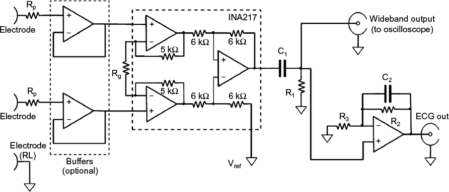 | Figure 1 Schematic of the wideband biopotential amplifier. Abbreviations: ECG, electrocardiography; RL, right leg; Rp, protection resistors (1.1 kΩ); Rg, instrumentation amplifier gain resistor (180 kΩ); C1 =4.7 mF, R1 =3.3 MΩ, passive high-pass filter; C2 =10 nF, R2 =100 kΩ, active low-pass filter; R3, active filter gain resistor (1 kΩ). |
The circuit is powered by a dual tension of ±9 V provided by two disposable batteries (not shown in Figure 1). The amplification of the first stage was kept small (ie, 10 V/V; Rγ=180 kΩ) in order to prevent the amplifier saturation,18 by considering the relatively high level of power line interference, electrode half-cell potentials, and also possible high amplitude of pacemaker pulses. The 10 V/V gain ensures a bandwidth from 0 Hz to, at least, 1 MHz. The input impedance offered by the INA217 is 60 MΩ, which is compliant with the ANSI/AAMI EC11 standard and therefore allows direct connection to patient’s electrodes. However, two simple op-amp-based unity-gain buffer amplifiers (eg, TL072) can be optionally added before instrumentation amplifier inputs to achieve much higher input impedances. However, it is wise to insert protection resistors in series with electrodes (Rp=1.1 kΩ in Figure 1) so as to limit patient’s currents, even in case of failure. At the instrumentation amplifier output, a passive, high-pass filter (C1=4.7 μF, R1=3.3 MΩ: cut-off frequency <0.05 Hz) blocks any offset and low frequencies of no clinical interest. After high-pass filtration, the signal is fed directly into a standard, battery-powered, oscilloscope to visualize pacemaker pulses.
A simultaneous, standard ECG derivation is provided by the active, low-pass filter (C2=10 nF, R2=100 kΩ, R3=1 kΩ), which limits the bandwidth to 150 Hz and provides an overall gain of 1,000 V/V. The entire circuit can be replicated to obtain multiple ECG leads. Assembled prototypes included a maximum of two parallel amplifiers (ie, standard ECG lead I and II), enough to obtain pacemaker vectorcardiogram on frontal plane.
The prototype systems were used, as additional diagnostic support, during periodic follow-up of pacemaker patients. As example of typical waveforms, Figures 2A and 3 show pulses generated by unipolar leads, while Figure 4 shows a waveform generated by a bipolar lead (much smaller in amplitude). Figure 2B presents the frontal plane vectorcardiogram obtained combining lead I and lead II (Figure 2A) data: the orientation of pulse vector corresponds to the direction of the line connecting the electrode and the pacemaker casing (this pacemaker device was implanted subcutaneously in the infraclavicular region, and the pacing electrode was placed in the right ventricle apex). From those figures, the characteristic shape of a pacemaker pulse can be clearly noted. It appears as the exponential discharge of the output capacitor into the lead load, limited to the programmed duration of the pulse. The leading and trailing edges of the pacemaker pulses usually last few microseconds (eg, those steepest 2–3 μs). Amplitudes of pulses change during the various phases of respiratory cycle (because of chest displacements and changes in thoracic impedance), similar to amplitudes of QRS in ECG recording.
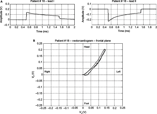 | Figure 2 Lead I and lead II pacemaker waveform and the corresponding vectorcardiogram Notes: (A) An example of monopolar pacemaker waveforms recorded from ECG lead I (upper trace) and from ECG lead II (lower trace). (B) Frontal plane vectorcardiogram of the pacemaker pulse. Abbreviation: ECG, electrocardiography. |
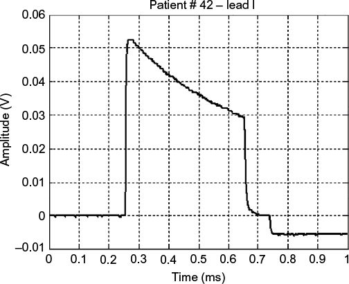 | Figure 3 An example of a monopolar pacemaker waveform recorded from ECG lead I. Abbreviation: ECG, electrocardiography. |
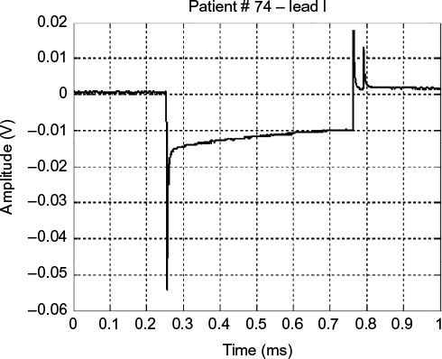 | Figure 4 An example of a bipolar pacemaker waveform recorded from ECG lead I. Abbreviation: ECG, electrocardiography. |
Figure 5 shows a waveform occasionally produced by a pacemaker with a defective output circuit, probably a bad electrical contact in the electrocatheter. The occurrence of this waveform type was occasional and, in some cases, associated with missed cardiac stimulation. After recording this anomaly, the patient was subjected to further medical examinations and finally underwent surgery to replace the whole implant.
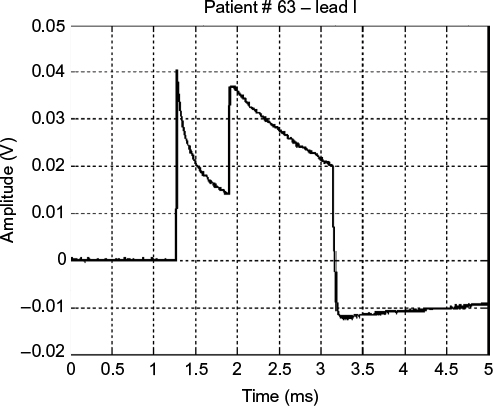 | Figure 5 Waveform of a monopolar pacemaker with a defective output circuit. Note: The image shows the abrupt disruption of the proper exponential decay signal. |
Conclusion
A biopotential amplifier with a bandwidth of ~1 MHz is proposed. The amplifier fulfils specifications suggested by international standard for electrocardiographic devices. The circuit is based on an integrated instrumentation amplifier (INA217) and has no need of calibration. Therefore, it can be simply embedded in various instrumentations that require highly accurate pacemaker pulse detection and timing. The wide bandwidth of the amplifier allows recording of accurate pacemaker pulse waveforms and also reproducing the fast-varying edges of pulses. Vectorcardiography of pacemaker pulses can be obtained by combining two or more amplifiers. In addition, the proposed circuit offers simultaneous conventional ECG signal as additional output.
This simple circuit can find application in equipment for the display and analysis of the waveforms produced by pacemaker and also where a precise timing of the pulses is required (eg, in biventricular pacing). It is also possible to precisely estimate the duration of each pulse, intertime between two pulses in magnetic mode (related to the state of charge of the battery), etc, of any pacemaker type, irrespective of availability of the specific programmer supplied by each manufacturer. In addition, analysis of pacemaker pulse droop (the exponential decay after the leading edge) can potentially provide interesting information about the lead impedance.19–21 Recently, some studies22,23 renewed the interest in the examination of pacemaker waveforms and have emphasized their potential to add new and detailed diagnostic information.24 The simplicity of realization of the proposed circuit and its possible use in clinical trials can promote the deepening of particular issues related to periodical monitoring of pacemaker implants. The circuit can be embedded in instrumentation for continuous monitoring of the ECG, such as Cardiac Holter monitors and other devices.25
Disclosure
The authors report no conflicts of interest in this work.
References
Uslan DZ, Tleyjeh IM, Baddour LM, et al. Temporal trends in permanent pacemaker implantation: a population-based study. Am Heart J. 2008;155(5):896–903. | ||
Writing Group Members, Roger VL, Go AS, et al; American Heart Association Statistics Committee and Stroke Statistics Subcommittee. Heart disease and stroke statistics 2012 update: a report from the American heart association. Circulation. 2012;125(1):e2–e220. | ||
Guglin ME, Datwani N. Electrocardiograms with pacemakers: accuracy of computer reading. J Electrocardiol. 2007;40(2):144–146. | ||
Poon K, Okin PM, Kligfield P. Diagnostic performance of a computer-based ECG rhythm algorithm. J Electrocardiol. 2005;38(3):235–238. | ||
Gulgin ME, Thatai D. Common errors in computer electrocardiogram interpretation. Int J Cardiol. 2006;106(2):232–237. | ||
Barold SS, Michael CG, Bengt H, Anne BC. Diagnostic value of the 12-lead electrocardiogram during conventional and biventricular pacing for cardiac resynchronization. Cardiol Clin. 2006;24:471–90. | ||
Kligfield P, Gettes LS, Bailey JJ, et al; American Heart Association Electrocardiography and Arrhythmias Committee, Council on Clinical Cardiology; American College of Cardiology Foundation; Heart Rhythm Society. Recommendations for the standardization and interpretation of the electrocardiogram: part I: the electrocardiogram and its technology a scientific statement from the American Heart Association Electrocardiography and Arrhythmias Committee, Council on Clinical Cardiology; the American College of Cardiology Foundation; and the Heart Rhythm Society endorsed by the International Society for Computerized Electrocardiology. J Am Coll Cardiol. 2007;49(10):1109–1127. | ||
American National Standard ANSI/AAMI EC11. Diagnostic Electrocardiographic Devices. Arlington, VA: Association for the Advancement of Medical Instrumentation (AAMI); 2007. | ||
International Standard IEC 60601-2-51. Medical Electrical Equipment Part 2–51: Particular Requirements for Safety, Including Essential Performance, of Recording and Analyzing Single Channel and Multichannel Electrocardiographs. Geneva: International Electrotechnical Commission (IEC); 2003. | ||
American National Standard ANSI/AAMI EC13. Cardiac Monitors, Heart Rate Meters, and Alarms. Arlington, VA: Association for the Advancement of Medical Instrumentation (AAMI); 2007. | ||
Ricke AD, Swiryn S, Bauernfeind RA, Conner JA, Young B, Rowlandson GI. Improved pacemaker pulse detection: clinical evaluation of a new high-bandwidth electrocardiographic system. J Electrocardiol. 2011;44(2):265–274. | ||
Grendahl H. Registration of pacemaker-induced skin potentials in the routine control of implanted pacemakers. Scand J Clin Lab Invest. 1969;24(3):251–259. | ||
Green GD, Forbes W, Bain WH, Shaw GB, Kenmure AC. Detection of faults in implanted cardiac pacemakers. Br Heart J. 1969;31(6):707–710. | ||
Davies JG, Siddons H. The detection of impending failure in implanted pacemakers. Thorax. 1969;24(1):74–77. | ||
International Standard IEC 60601-1. Medical Electrical Equipment – Part 1: General Requirements for Basic Safety and Essential Performance. Geneva: International Electrotechnical Commission (IEC); 2012. | ||
Sowton E, Gray K. Clinical testing of implanted pacemakers. Thorax. 1971;26(2):145–154. | ||
Hepburn F. Discriminating between types of pacemaker lead failure. J Med Eng Technol. 1978;2(3):130–135. | ||
Gargiulo G, Bifulco P, Cesarelli M, et al. An ultra-high input impedance ECG amplifier for long-term monitoring of athletes. Med Dev (Auckl). 2010;3:1–9. | ||
Anelli-Monti M, Mächler H, Oberwalder O, Knez I, Dacar D, Rigler B. Lead stability in long-term follow-up of bipolar leads. Wien Med Wochenschr. 2000;150(19–21):414–418. | ||
Dorwarth U, Frey B, Dugas M, et al. Transvenous defibrillation leads: high incidence of failure during long-term follow-up. J Cardiovasc Electrophysiol. 2003;14(1):38–43. | ||
Luria D, Glikson M, Brady PA, et al. Predictors and mode of detection of transvenous lead malfunction in implantable defibrillators. Am J Cardiol. 2001;87(7):901–904. | ||
Bartsch C, Irnich W, Risse M, Junge M, Weiler G. Postmortem in situ diagnosis of pacemakers and electrodes to detect dysfunction. Leg Med (Tokyo). 2003;5(suppl 1):S397–S400. | ||
Bartsch C, Irnich W, Junge M, Stertmann WA, Risse M, Weiler G. Post-mortem evaluation of 415 pacemakers: in situ measurements and bench tests. Europace. 2005;7(2):175–180. | ||
Tannenberg M, Sepsi M. Measurement and significance of pacemaker pulse parameters. World Congr Med Phys Biomed Eng. 2006;2(06):769–772. | ||
Gargiulo G, Bifulco P, Cesarelli M, Jin C, McEwan A, Van Schaik A. Wearable dry sensors with bluetooth connection for use in remote patient monitoring systems. Stud Health Technol Inform. 2010;161:57–65. |
 © 2016 The Author(s). This work is published and licensed by Dove Medical Press Limited. The full terms of this license are available at https://www.dovepress.com/terms.php and incorporate the Creative Commons Attribution - Non Commercial (unported, v3.0) License.
By accessing the work you hereby accept the Terms. Non-commercial uses of the work are permitted without any further permission from Dove Medical Press Limited, provided the work is properly attributed. For permission for commercial use of this work, please see paragraphs 4.2 and 5 of our Terms.
© 2016 The Author(s). This work is published and licensed by Dove Medical Press Limited. The full terms of this license are available at https://www.dovepress.com/terms.php and incorporate the Creative Commons Attribution - Non Commercial (unported, v3.0) License.
By accessing the work you hereby accept the Terms. Non-commercial uses of the work are permitted without any further permission from Dove Medical Press Limited, provided the work is properly attributed. For permission for commercial use of this work, please see paragraphs 4.2 and 5 of our Terms.