")
Back to Journals » Clinical Interventions in Aging » Volume 16
A Minimally Invasive Technique Using Cortical Bone Trajectory Screws Assisted by 3D-Printed Navigation Templates in Lumbar Adjacent Segment Degeneration
Authors He K , Dong C , Wei H , Yang F, Ma H, Tang X, Tan M, Yi P
Received 3 May 2021
Accepted for publication 25 June 2021
Published 20 July 2021 Volume 2021:16 Pages 1403—1413
DOI https://doi.org/10.2147/CIA.S318525
Checked for plagiarism Yes
Review by Single anonymous peer review
Peer reviewer comments 2
Editor who approved publication: Dr Zhi-Ying Wu
Kun He,1,2,* Chunke Dong,3,* Hongyu Wei,2,* Feng Yang,2 Haoning Ma,2 Xiangsheng Tang,2 Mingsheng Tan,2 Ping Yi2
1Beijing University of Chinese Medicine, Beijing, 100029, People’s Republic of China; 2Department of Orthopaedic Surgery, China-Japan Friendship Hospital, Beijing, 100029, People’s Republic of China; 3Beijing Hospital of Traditional Chinese Medicine, Capital Medical University, Beijing, 100010, People’s Republic of China
*These authors contributed equally to this work
Correspondence: Ping Yi; Mingsheng Tan Email [email protected]; [email protected]
Purpose: Revision surgery for adjacent segment degeneration (ASD) commonly requires exposing and removing the original fixation. To minimize trauma and to reduce the operation time and blood loss, we introduced a minimally invasive lumbar revision technique using cortical bone trajectory (CBT) screws assisted by three-dimensional (3D)-printed navigation templates.
Methods: From April 2017 to October 2019, 18 patients with ASD underwent revision surgery with CBT screws assisted by 3D-printed templates in our hospital. All surgical data, including the operation time, blood loss, and incision length, were recorded. We evaluated the clinical efficacy using the visual analog scale (VAS), the Oswestry Disability Index (ODI), and the Japanese Orthopedic Association (JOA) score. X-ray and computed tomography (CT) scans were used to evaluate the stability of CBT screw fixation, the accuracy of screws, and the fusion rate.
Results: The mean follow-up was 22.4± 4.7 months (12– 31 months). The VAS, ODI, and JOA scores were analyzed by SPSS 21.0 and showed significant improvement at 2 weeks and the last follow-up compared with preoperative data (P< 0.05). Seventy-six CBT screws were inserted with navigation templates; 2 screws were Grade B, and the other screws were Grade 0 or A. Changes in intervertebral height showed good stability of CBT screw fixation (P> 0.05). All the patients exhibited satisfactory fusion results.
Conclusion: Revision surgery for ASD with CBT screws assisted by 3D-printed navigation templates has satisfactory clinical efficacy with the advantages of a short operation time, a small incision, and less blood loss.
Keywords: adjacent segment degeneration, cortical bone trajectory, revision surgery, 3D printing, navigation template
Introduction
Lumbar fusion with pedicle screw fixation is widely used in lumbar degenerative diseases due to its definite clinical efficacy.1,2 However, because of the local biomechanical structural changes caused by exposure, iatrogenic injury to facet joints, and fusion, adjacent segment degeneration (ASD) is regarded as a common long-term complication of fusion surgery.3–5 Recently, a meta-analysis reported that the incidence of radiological adjacent segment disease (R-ASD) was 27.8%, the incidence of symptomatic adjacent segment disease (S-ASD) was 7.6%, and the revision surgery rate was 4.6%.6
For patients with obvious clinical symptoms who require revision surgery, we routinely need to remove the original connecting rod and reinstall the rod after inserting new screws in the adjacent vertebra. The operation requires exposure of the original surgical incision, which is more traumatic and prone to bleeding and takes a long time.7,8 Moreover, the incidence of postoperative pain and infection is relatively high. Some scholars reported that cortical bone trajectory (CBT) screws could be inserted into the segment that had been previously inserted into the original pedicle screw by the free-hand technique or via the intraoperative navigation system. In this way, they performed revision surgery without removing the original connecting rods, and satisfactory clinical results were achieved.9,10 However, because the original pedicle screw occupies the space of the pedicle, inserting CBT screws in the same pedicle requires high accuracy. The free-hand technique is likely to cause complications related to internal fixation, including nerve and blood vessel damage and other adverse events. Intraoperative navigation technology incurs high costs, increasing the operation time and the patient’s radiation exposure. Considering that 3D-printing technology is very mature and widely used in spine surgery, we used 3D-printing technology to make screw navigation templates to assist CBT screw placement and achieved satisfactory clinical effects. The report is as follows.
Materials and Methods
Patients
This study reviewed a total of 18 patients (M: F=7:11) with an average age of 67.1 years (range: from 54 to 79 years) with ASD from April 2017 to October 2019 in our hospital who underwent revision surgery using CBT screws and 3D-printed navigation templates. One patient had ASD combined with thoracic spinal stenosis and underwent ASD revision combined with thoracic spinal canal decompression and fixation. Another patient had ASD on both the cephalad and caudal sides of the original operation segments; the rest of the patients had unilateral (cephalad or caudal) ASD and received one segment revision surgery (Table 1).
 |
Table 1 General Information and Operative Data of 18 Patients |
Preoperative Planning & 3D Printing
All patients underwent a thin-slice CT scan (1 mm) before the operation, and the data were imported into Mimics 20.0 (Materialistic, Belgium) software for three-dimensional reconstruction. A 4.5 mm diameter cylinder simulating the CBT screw was drawn, and the trajectory was planned through the axial, sagittal, and coronal perspectives to ensure that the CBT screw was not in contact with the original pedicle screw and to stay close to the pedicle cortex. Making a 2.7 mm diameter drill guide hole in the 4.5 mm cylinder and using the spinous process, the lamina, and the original pedicle screw as the contact point to create the contact surface of the navigation template. Combining the drill guide hole and the contact surface, and making a connect bridge between the contact surface on both sides so that the navigation template was completed. The template was printed and sterilized before surgery (Figure 1).
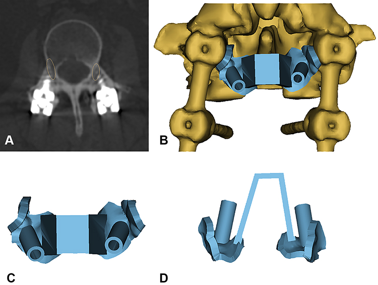 |
Figure 1 Preoperative plan and 3D model of the navigation template. (A) The yellow ellipses indicate the CBT screw trajectory planned before the surgery. (B) The navigation template with the segment with the original pedicle screw reconstructed by Mimics. (C and D) The top and back view of the navigation template. |
Surgical Procedure & Postoperative Care
After general anesthesia, the patient lay prone on the spine operating table, exposing the lamina isthmus and the inner edge of the facet joint. The soft tissue was carefully cleaned to ensure that the screw navigation template was fully attached to the bone surface and the original screws. Drilled and tapped along the pilot hole, the screw path was carefully probed with a ball-tip probe to confirm that the four walls of the pedicle were complete, and a 4.5 mm diameter CBT screw was inserted. Posterior lumbar interbody fusion (PLIF) was continued conventionally, and one cage was inserted (if the CBT screw affected cage implantation, the cage was implanted first, and then the screw was inserted). The position of the screw and cage was satisfied by fluoroscopy. After flushing, the drainage tube was inserted, and the wound was sutured. On the second day after the operation, the drainage tube was pulled out. On the third day, the patients would get out of bed, protected by a waist brace. Typical cases are shown in Figures 2–4 (Figures 2–4).
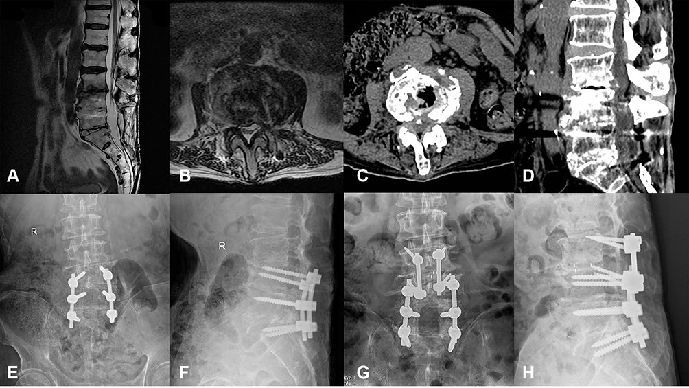 |
Figure 2 Case 1. A 77-year-old man with ASD of L3-4 underwent revision surgery with CBT screws assisted by a navigation template. (A–D) Preoperative MRI and CT scans revealed L3/4 intervertebral disc herniation and calcification. (E–H) His pre- and postoperative X-ray showed the CBT screws as the fixation method for L3/4. |
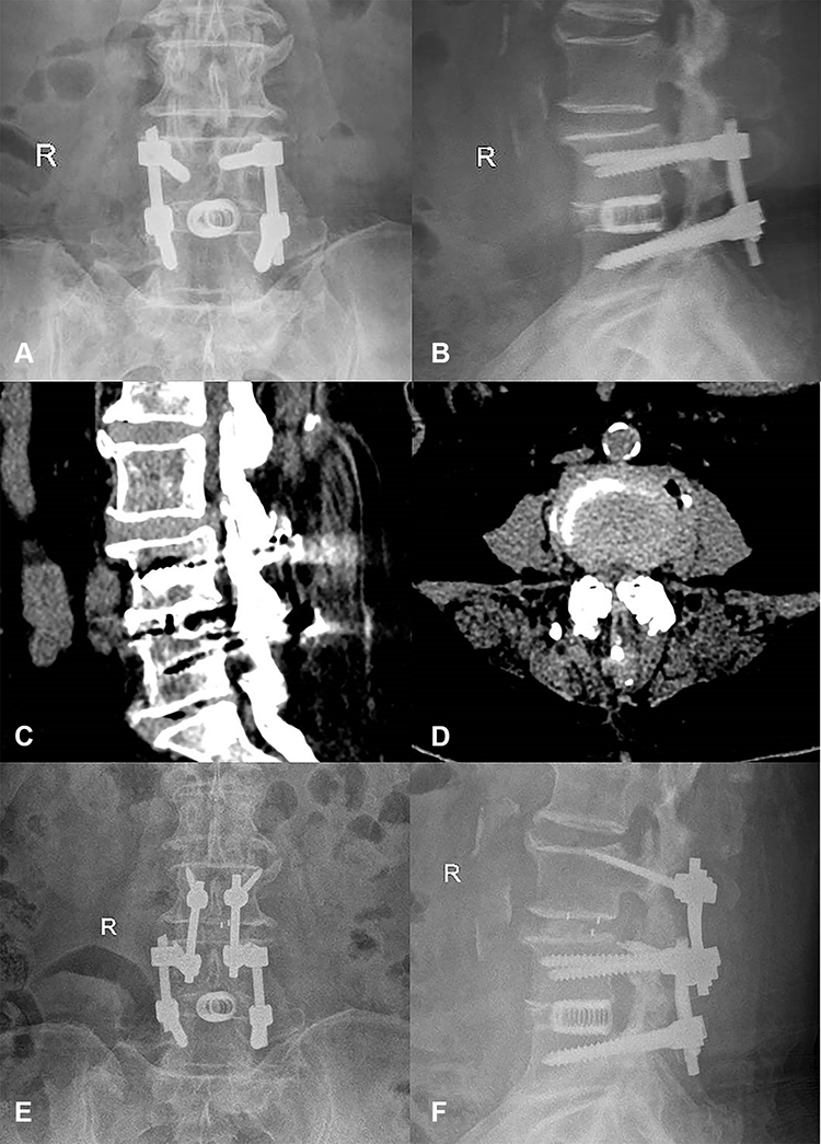 |
Figure 3 Case 2. A 63-year-old female had undergone L4/5 fusion 5 years prior. She had experienced radiating pain of the left lower limb for half a year and was diagnosed with ASD of L3/4. (A and B) Preoperative X-ray showed the original pedicle screws and cage in L4/5. (C and D) Preoperative CT revealed L3/4 intervertebral disc herniation. (E and F) X-ray after the surgery showed good positioning of the CBT screws. |
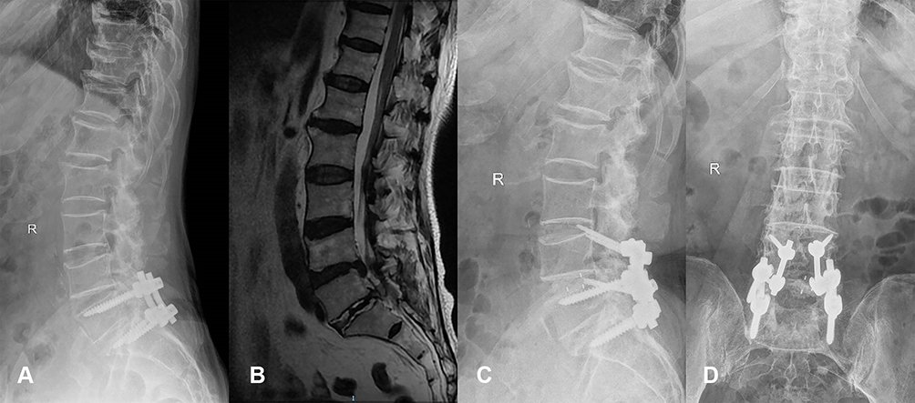 |
Figure 4 Case 3. A 58-year-old female had undergone prior L5/S1 fusion. She had ASD of L4/5 at the current presentation. (A) Preoperative X-ray showed original fixation of L5/S1. (B) Preoperative MRI revealed a disc herniated into the spinal canal. (C and D) X-ray after the surgery showed good positioning of the CBT screws. |
Evaluation
All operative data, including the operation time, incision length, estimated bleeding volume, etc. were recorded. The visual analog scale (VAS), the Oswestry Disability Index (ODI), and the Japanese Orthopedic Association (JOA) score were assessed before the surgery, 2 weeks after the surgery and at the last follow-up to evaluate the clinical efficacy. Intervertebral heights were measured as the average height of the anterior and posterior intervertebral space by lateral X-ray before the surgery, 2 weeks after the surgery and at the last follow-up to evaluate the stability of fixation.11,12 CT scans were taken at the last follow-up to evaluate the position of the screws and the fusion of the surgical segment.
Statistical Analysis
Statistical analysis was performed with SPSS 21.0 (SPSS, Inc., Chicago, IL, USA). All general information and operative data are expressed as the mean ± standard deviation (SD). Measurement data were compared using the paired t-test. The Wilcoxon signed rank test was used for nonparametric comparisons. P<0.05 was considered statistically significant.
Result
A total of 76 CBT screws were inserted in 18 patients by the same surgical team (average surgery experience more than 10 years) using 3D-printed navigation templates. The average operation time was 154±58 min, the blood loss was 144±176 mL, and the incision length was 6.8±4.2 cm (Table 1). According to the standard proposed by Gertzbein,13 54 screws were classified as Grade 0, 20 screws were classified as Grade A, 2 screws were classified as Grade B, and no screw was classified as Grade C. One patient had left radicular pain after surgery. A CT scan showed that one CBT screw had broken through the inferior wall of the pedicle. The symptoms were relieved after a second operation performed to adjust the screw position. One patient had a rupture of the spine dura mater and leakage of cerebrospinal fluid due to scar adhesion during the operation. The dura mater was repaired, and the drainage tube was removed after the patient lay in bed for a week after the operation. One patient had a postoperative fever and painful urination, and routine urine tests suggested urinary system infection. The infection improved after levofloxacin anti-infective treatment. The remaining patients had no perioperative complications.
The mean follow-up time was 22.4±4.7 months (12–31 m). The VAS score was 6.6±1.2 before the operation, 3.3±2.0 at 2 weeks after the operation and 1.6±1.0 at the last follow-up. The ODI (%) was 43.9±9.4 before the operation, 24.6±5.1 at 2 weeks after the operation, and 12.8±3.9 at the last follow-up. The JOA score was 14.6±2.9 before the operation, 20.5±5.1 at 2 weeks after the operation, and 23.8±1.5 at the last follow-up. The VAS, ODI, and JOA scores were statistically significant at 2 weeks after the operation and at the last follow-up, compared with the data before the operation (P<0.05). The intervertebral height (mm) before the operation, 2 weeks after the operation, and at the last follow-up were 7.8±2.3, 10.8±1.3, and 10.5±1.4, respectively. Compared with the preoperative value, the intervertebral height was significantly different at 2 weeks and at the last follow-up (P<0.05), but there was no significant difference between the 2-week follow-up and the last follow-up values (P>0.05) (Figure 5). Evaluations by CT scans showed that all patients achieved satisfactory fusion as of the last follow-up.
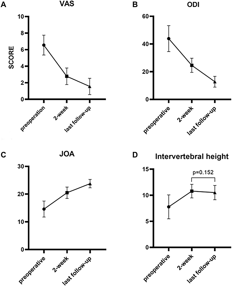 |
Figure 5 The VAS, ODI, JOA score, and intervertebral height in different assessments. (A) The VAS scores before the operation, 2 weeks after the operation, and at the last follow-up were 6.6±1.2, 3.3±2.0, and 1.6±1.0, respectively; (B) the ODI scores before the operation, 2 weeks after the operation, and at the last follow-up were 43.9±9.4, 24.6±5.1, and 12.8±3.9, respectively; (C) the JOA scores before the operation, 2 weeks after the operation, and at the last follow-up were 14.6±2.9, 20.5±5.1, and 23.8±1.5, respectively. These differences were all statistically significant (P<0.05). (D) The intervertebral heights (mm) before the operation, 2 weeks after the operation, and at the last follow-up were 7.8±2.3, 10.8±1.3, and 10.5±1.4, respectively. There was no significant difference between 2 weeks and the last follow-up (P>0.05). |
Discussion
CBT screws were first used for posterior spinal fixation in patients with osteoporosis as reported by Santoni et al, and this procedure maximizes contact with cortical bone.14 Because it has a medial-to-lateral direction and a caudocephalad trajectory, the CBT screw can reduce soft tissue separation, minimize trauma and blood loss, and shorten the operation time.15 Sakaura et al found that CBT screws can reduce the incidence of radiological adjacent segment disease changes (R-ASD) and symptomatic adjacent segment disease (S-ASD) by protecting cephalic facet joints.16 Biomechanical studies have shown that CBT screws have 1.7 times the pull-out resistance of traditional pedicle screws,17 and the clinical efficacy in posterior lumbar fusion is equivalent to that of traditional pedicle screws.18 As an alternative technique of internal fixation of the spine, CBT screws have been extensively studied by orthopedic surgeons.
In recent years, some scholars have adopted the method of simultaneously inserting pedicle screws and CBT screws into the same pedicle to solve some complicated spinal diseases. Ueno used the double-trajectory technique in a patient with severe osteoporosis and achieved satisfaction fixation effects.19 Analiz Rodriguez et al used a navigation system to insert CBT screws in the same pedicle with pedicle screws to perform revision surgery for ASD, whereas Chen et al used a free-hand technique; both procedures yielded satisfactory results.9,10 Obviously, the CBT screw used for ASD revision surgery does not need the original fixation to be removed, which has many advantages, such as a small surgical incision, less trauma, a short operation time, and less blood loss. The longer the original surgical segment, the more apparent are these advantages.
However, the difficulty of this procedure was that the pedicle screw and CBT screw are placed in the same pedicle at the same time. Although the pedicle screw and CBT screw have different start points and trajectories, in many cases, these two screw placement channels still have a certain degree of overlap, and the double screws collide in the pedicle (Figure 6). After radiological measurements and research, Mullin found that the success rate of inserting pedicle screws and CBT screws in the same pedicle was approximately 50%,20 so it is essential to analyze CT carefully before surgery and plan a feasible screw placement trajectory. An intraoperative navigation system has been used to improve the accuracy of screw placement.9 However, this navigation system is expensive and complicated to operate; it generally requires a special operating room layout and technical personnel to assist operations, and the use of a navigation system is reported to involve higher radiation exposure.21 More importantly, even if the preoperative CT scan is confirmed to have a feasible screw trajectory, it is still challenging to find the trajectory again during the operation. Due to the influence of factors such as the surgical position and the positioning of the navigation system, the trajectory may be different from that in the preoperative plan, and the optimal trajectory may thus deviate. When the optimal trajectory has been selected via preoperative CT, the production of navigation templates yields a very mature technology with low cost.
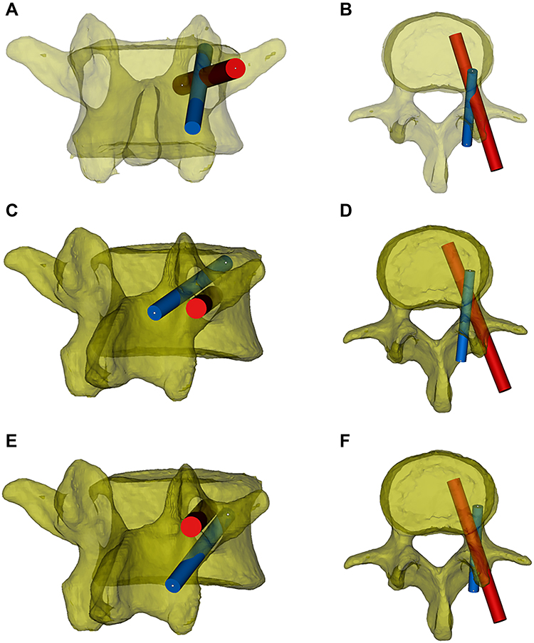 |
Figure 6 The trajectory relationship between the pedicle screw and CBT screw. The red cylinder represents the pedicle screw, and the blue cylinder represents the CBT screw. (A and B) Using the standard screw placement technique, the trajectories of the pedicle screws and CBT screws partially overlap in the pedicle. (C and D) The original pedicle is close to the inferior wall of the pedicle, and the new CBT screw will course along the superior aspect of the original pedicle screw. (E and F) The original pedicle is close to the superior wall of the pedicle, and the new CBT screw will course under the original pedicle screw. |
The use of individual templates in orthopedics was first reported by Radermacher in 1998.22 With the improvement of 3D-printing technology, it has been used more widely, especially in spine surgery. The technology of making screw navigation templates is mature and relatively economical. Many researchers use 3D-printing technology to create navigation templates to assist the placement of cervical pedicle screws, thoracic pedicle screws, and CBT screws or to assist screw placement in special cases such as severe spinal deformity and complex revision surgery; these approaches have been proven to have higher accuracy and safety and to help reduce the radiation exposure of both the patients and operating room staff.23–26 The use of 3D-printed navigation templates can also reduce surgical bleeding. However, 3D-printed navigation templates also have some defects. Although the price is relatively low, 3D-printed navigation templates still increase the cost and workload. To increase the stability of the guide, it is often necessary to separate more soft tissues, which may cause iatrogenic injury. However, this procedure may not cause more bleeding according to a meta-analysis, and the possible reasons may be that the soft tissue injury is small and there is less need to adjust the screw position.27 It takes approximately 2 days to create the 3D-printed navigation templates; consequently, this technique is not suitable for emergency surgery.
In our study, we used 3D-printed navigation templates to assist the placement of CBT screws into the vertebral body; pedicle screws were inserted in 18 cases, and the rest of the surgical procedures were the same as conventional techniques. Compared with navigation technology, our operation time is shorter (154±58 min), and the blood loss during the operation is less (144±176 mL).9 Moreover, the cost of making the navigation template is relatively low. We estimate that the cost of navigation-template creation is 400 dollars per segment, and the cost of using CT navigation equipment may be as high as 1500–2000 dollars. The navigation template is completed before the operation. Although the workload is slightly increased, there are almost no extra steps during the operation, so we think this approach is worthwhile. In addition, this technique does not have any extra learning curves, and 3D-printing devices are easy to obtain (or the navigation templates can be made by a cooperative company). Considering factors such as difficulty and cost, we believe that screw placement assisted by the 3D-printed navigation template has certain advantages compared with the intraoperative CT navigation system and that it is easier to promote and apply, especially in primary hospitals.
In this study, the newly inserted CBT screws ran along the superior or inferior of the original pedicle screw from the inner to the outer side, mainly based on preoperative CT planning, the space that allows the new CBT screw to be inserted (Figure 6). During the preoperative planning, some of the CBT screws could not reach the cortical bone of the superior endplate because of blocking by the original pedicle screw. Therefore, we increased the abduction angle of the screw so that the screw just reached or penetrated the pedicle and the outer edge of the vertebral cortex. Considering that there are no essential nerves, blood vessels or other anatomical structures, the screw fixation strength can be increased to prevent internal fixation failure. This increases the number of screws classified as Grade A-B when we evaluate the accuracy of the screw after surgery, but because most of our screws slightly broke through the outer wall of the pedicle at the end (except for one Grade B screw, which resulted in nerve root stimulation after breaking through the inferior wall of the pedicle), none of the other screws have caused postoperative complications related to internal fixation. Ueno reported that the starting point of the newly inserted CBT screw based on the original pedicle screw should be located above the conventional CBT screws, so the CBT screws will run along the superior of the original pedicle screw,19 but in this way, the CBT screw cannot interact with the inner and inferior wall of the pedicle, which may weaken the fixation strength of the screw. It has also been reported in the literature that the CBT screw should be run obliquely from the inner and inferior aspect of the pedicle screw to the outer and superior aspect so that the screw has a stronger fixation strength.28 However, this approach may be limited by the size of the pedicle and the position of the original pedicle screw, and because the nerve root is often close to the inner and inferior wall of the pedicle, this method of screw placement is more likely to cause nerve injury. One of our patients had right pedicle pain after surgery; in this case, the CBT screw broke through the inner and inferior walls of the pedicle. In our study, we evaluated the stability of fixation by measuring the intervertebral height pre- and postoperatively, and the results showed that the postoperative and last follow-up intervertebral heights were significantly greater than those before the operation. Meanwhile, the postoperative data and the last follow-up data were not significantly different. The CT scan also showed good fusion at the last follow-up, so we considered fixation using CBT screws as yielding satisfactory stability. However, this method should be tested by biomechanical tests in the future.
Accurate attachment of the navigation template is the key to the accuracy of the screw position. In an RCT study of 3D-printed navigation template-assisted screw placement in patients with spinal deformity, Riccardo et al reported that 9.8% of the screws in the 3D-printed navigation template group were graded as Grade B or C.23 Evan D. Sheha believed that this situation is mainly due to the poor fit between the navigation template and the bone surface.29 In the present study, we summarize the experience in the process of making the navigation template: Because the facet joints of the revision surgery are mostly damaged during the first operation and the surrounding soft tissues and scars are severely proliferated, it is difficult to clean the surface of the facet joint during the revision process, so it is not suitable as a navigation template attachment point. In contrast, the original internal fixation screws are fixed in position, and the surface soft tissue is easy to clean and remove. In Mimics modeling, due to the high Hounsfield unit (HU) of the original screws on CT, the density of the surrounding soft tissue and bone tissue differs, the boundary is clear, and the modeling accuracy is high. Therefore, we used the inner edge of the original fixation screw and the spinous process bone surface as the main contact surface of the screw navigation template. Meanwhile, a connect bridge was necessary because it could also increase the stability of the navigation template.
Limitation
There are some limitations of this study. First, it was retrospective, there was no control group, and the total number of cases was only 18. Although 18 patients achieved satisfactory fusion at the last follow-up, future studies with larger sample sizes are needed to validate the fusion rate due to this small number of cases. Second, CBT screws cannot always be used for revision surgery of adjacent segments because of anatomical limitations. Nevertheless, we still recommend this technique for clinical application because multiple studies, including ours, have confirmed good clinical results.9,10 Once the screws were successfully inserted by the abovementioned technique, the patients benefited greatly. Third, due to the existence of the original pedicle screw, the trajectory of the CBT needs to be compromised, which may cause some CBT screws to fail to achieve the maximum cortical contact as has been reported for the “4-point cortical contact”;30 consequently, systematic biomechanical stability research of this fixation method is required in the future.
Conclusion
CBT screw revision for ASD greatly optimizes the operation plan because it does not need to remove the original fixation. The application of a 3D-printed navigation template to assist the placement of CBT screws can be planned before surgery and accurately placed during surgery. In addition, 3D-printing technology is mature and low in cost. Thus, it is worth being promoted and applied in ASD revision surgery. As a new type of internal fixation with a different insertion point and trajectory from traditional pedicle screws, CBT screws may coexist with pedicle screws in the same pedicle, greatly expanding the internal fixation and its connection. This method can play a variety of roles in complex spinal diseases and should be further explored and applied.
Abbreviations
ASD, adjacent segment degeneration; CBT, cortical bone trajectory; 3D, three-dimensional; VAS, visual analog scale; ODI, Oswestry Disability Index; JOA, Japanese Orthopedic Association; CT, computed tomography; MRI, magnetic resonance imaging; R-ASD, radiological adjacent segment disease; S-ASD, symptomatic adjacent segment disease; PLIF, posterior lumbar interbody fusion.
Data Sharing Statement
The datasets analyzed during the current study are available from the corresponding author on reasonable request. Corresponding Author: Ping Yi, Email: [email protected] and Mingsheng Tan, Email: [email protected].
Ethics Approval and Informed Consent
This retrospective study was approved by the institutional ethics committee of the China-Japan Friendship Hospital. Informed consent was obtained from patient included in the study. All procedures were performed in accordance with the ethical standards of our institutional and national research committees and within the bounds of the 1964 Helsinki declaration and its later amendments.
Consent for Publication
This study has obtained the consent for publication from all participations.
Disclosure
The authors declare that they have no conflicts of interest in this work.
References
1. Fritzell P, Hägg O, Wessberg P, Nordwall A, Swedish Lumbar Spine Study Group. 2001 Volvo Award Winner in Clinical Studies: lumbar fusion versus nonsurgical treatment for chronic low back pain: a multicenter randomized controlled trial from the Swedish Lumbar Spine Study Group. Spine (Phila Pa 1976). 2001;26(23):2521–2534. doi:10.1097/00007632-200112010-00002
2. Malmivaara A, Slätis P, Heliövaara M, et al. Surgical or nonoperative treatment for lumbar spinal stenosis? A randomized controlled trial. Spine (Phila Pa 1976). 2007;32(1):1–8. doi:10.1097/01.brs.0000251014.81875.6d
3. Ghiselli G, Wang JC, Bhatia NN, Hsu WK, Dawson EG. Adjacent segment degeneration in the lumbar spine. J Bone Joint Surg Am. 2004;86(7):1497–1503. doi:10.2106/00004623-200407000-00020
4. Di Martino A, Quattrocchi CC, Scarciolla L, Papapietro N, Beomonte Zobel B, Denaro V. Estimating the risk for symptomatic adjacent segment degeneration after lumbar fusion: analysis from a cohort of patients undergoing revision surgery. Eur Spine J. 2014;23(Suppl 6):693–698. doi:10.1007/s00586-014-3551-0
5. Heo Y, Park JH, Seong HY, et al. Symptomatic adjacent segment degeneration at the L3-4 level after fusion surgery at the L4-5 level: evaluation of the risk factors and 10-year incidence. Eur Spine J. 2015;24(11):2474–2480. doi:10.1007/s00586-015-4188-3
6. Donnally CJ
7. Whitecloud TS
8. Tu Z, Li L, Wang B, Li Y, Lv G. Stand-Alone Anterolateral Interbody Fusion Versus Extended Posterior Fusion for Symptomatic Adjacent-Segment Degeneration: a Retrospective Study of 2 Years’ Follow-up. World Neurosurg. 2018;115:e748–e755. doi:10.1016/j.wneu.2018.04.165
9. Rodriguez A, Neal MT, Liu A, Somasundaram A, Hsu W, Branch CL
10. Chen CH, Huang HM, Chen DC, Wu CY, Lee HC, Cho DY. Cortical bone trajectory screws fixation in lumbar adjacent segment disease: a technique note with case series. J Clin Neurosci. 2018;48:224–228. doi:10.1016/j.jocn.2017.11.008
11. Zhong HZ, Tian DS, Zhou Y, et al. Comparing the early efficacies of autologous bone grafting and interbody fusion cages for treating degenerative lumbar instability in patients of different ages. Int Orthop. 2016;40(6):1211–1218. doi:10.1007/s00264-016-3124-4
12. Peng D, Ma Y, Lei B. Clinical and Radiological Outcomes of Anterior Approach Microscopic Surgery for the Pincer Mechanism in Cervical Spondylotic Myelopathy. Biomed Res Int. 2019;9175234. doi:10.1155/2019/9175234
13. Gertzbein SD, Robbins SE. Accuracy of pedicular screw placement in vivo. Spine (Phila Pa 1976). 1990;15(1):11–14. doi:10.1097/00007632-199001000-00004
14. Santoni BG, Hynes RA, McGilvray KC, et al. Cortical bone trajectory for lumbar pedicle screws. Spine J. 2009;9(5):366–373. doi:10.1016/j.spinee.2008.07.008
15. Hu JN, Yang XF, Li CM, Li XX, Ding YZ. Comparison of cortical bone trajectory versus pedicle screw techniques in lumbar fusion surgery: a meta-analysis. Medicine (Baltimore). 2019;98(33):e16751. doi:10.1097/MD.0000000000016751
16. Sakaura H, Ikegami D, Fujimori T, et al. Early cephalad adjacent segment degeneration after posterior lumbar interbody fusion: a comparative study between cortical bone trajectory screw fixation and traditional trajectory screw fixation. J Neurosurg Spine. 2019;32(2):155–159. doi:10.3171/2019.8.SPINE19631
17. Matsukawa K, Yato Y, Kato T, Imabayashi H, Asazuma T, Nemoto K. In vivo analysis of insertional torque during pedicle screwing using cortical bone trajectory technique. Spine (Phila Pa 1976). 2014;39(4):E240–E245. doi:10.1097/BRS.0000000000000116
18. Wang J, He X, Sun T. Comparative clinical efficacy and safety of cortical bone trajectory screw fixation and traditional pedicle screw fixation in posterior lumbar fusion: a systematic review and meta-analysis. Eur Spine J. 2019;28(7):1678–1689. doi:10.1007/s00586-019-05999-y
19. Ueno M, Imura T, Inoue G, Takaso M. Posterior corrective fusion using a double-trajectory technique (cortical bone trajectory combined with traditional trajectory) for degenerative lumbar scoliosis with osteoporosis: technical note. J Neurosurg Spine. 2013;19(5):600–607. doi:10.3171/2013.7.SPINE13191
20. Mullin JP, Perlmutter B, Schmidt E, Benzel E, Steinmetz MP. Radiographic feasibility study of cortical bone trajectory and traditional pedicle screw dual trajectories. J Neurosurg Spine. 2016;25(6):727–732. doi:10.3171/2016.4.SPINE151483
21. Pitteloud N, Gamulin A, Barea C, Damet J, Racloz G, Sans-Merce M. Radiation exposure using the O-arm® surgical imaging system. Eur Spine J. 2017;26(3):651–657. doi:10.1007/s00586-016-4773-0
22. Radermacher K, Portheine F, Anton M, et al. Computer assisted orthopaedic surgery with image based individual templates. Clin Orthop Relat Res. 1998;354:28–38. doi:10.1097/00003086-199809000-00005
23. Cecchinato R, Berjano P, Zerbi A, Damilano M, Redaelli A, Lamartina C. Pedicle screw insertion with patient-specific 3D-printed guides based on low-dose CT scan is more accurate than free-hand technique in spine deformity patients: a prospective, randomized clinical trial. Eur Spine J. 2019;28(7):1712–1723. doi:10.1007/s00586-019-05978-3
24. Wang K, Zhang ZJ, Chen JX, Wu AM, Wang XY, Sheng SR. Design and Application of Individualized, 3-Dimensional-Printed Navigation Template for Placing Cortical Bone Trajectory Screws in Middle-Upper Thoracic Spine: cadaver Research Study. World Neurosurg. 2019;125:e348–e352. doi:10.1016/j.wneu.2019.01.076
25. Matsukawa K, Kaito T, Abe Y. Accuracy of cortical bone trajectory screw placement using patient-specific template guide system. Neurosurg Rev. 2020;43(4):1135–1142. doi:10.1007/s10143-019-01140-1
26. Li Y, Lin J, Wang Y, et al. Comparative study of 3D printed navigation template-assisted atlantoaxial pedicle screws versus free-hand screws for type II odontoid fractures. Eur Spine J. 2021;30(2):498–506. doi:10.1007/s00586-020-06644-9
27. Liang W, Han B, Hai JJ, et al. 3D-printed drill guide template, a promising tool to improve pedicle screw placement accuracy in spinal deformity surgery:</L> A systematic review and meta-analysis [published online ahead of print, 2021 Feb 8]. Eur Spine J. 2021. doi:10.1007/s00586-021-06739-x
28. Matsukawa K, Yato Y, Imabayashi H, Hosogane N, Asazuma T, Nemoto K. Biomechanical Evaluation of Cross Trajectory Technique for Pedicle Screw Insertion: combined Use of Traditional Trajectory and Cortical Bone Trajectory. Orthop Surg. 2015;7(4):317–323. doi:10.1111/os.12212
29. Sheha ED, Gandhi SD, Colman MW. 3D printing in spine surgery. Ann Transl Med. 2019;7(Suppl 5):S164. doi:10.21037/atm.2019.08.88
30. Matsukawa K, Yato Y, Nemoto O, Imabayashi H, Asazuma T, Nemoto K. Morphometric measurement of cortical bone trajectory for lumbar pedicle screw insertion using computed tomography. J Spinal Disord Tech. 2013;26(6):E248–E253. doi:10.1097/BSD.0b013e318288ac39
 © 2021 The Author(s). This work is published and licensed by Dove Medical Press Limited. The full terms of this license are available at https://www.dovepress.com/terms.php and incorporate the Creative Commons Attribution - Non Commercial (unported, v3.0) License.
By accessing the work you hereby accept the Terms. Non-commercial uses of the work are permitted without any further permission from Dove Medical Press Limited, provided the work is properly attributed. For permission for commercial use of this work, please see paragraphs 4.2 and 5 of our Terms.
© 2021 The Author(s). This work is published and licensed by Dove Medical Press Limited. The full terms of this license are available at https://www.dovepress.com/terms.php and incorporate the Creative Commons Attribution - Non Commercial (unported, v3.0) License.
By accessing the work you hereby accept the Terms. Non-commercial uses of the work are permitted without any further permission from Dove Medical Press Limited, provided the work is properly attributed. For permission for commercial use of this work, please see paragraphs 4.2 and 5 of our Terms.