")
Back to Journals » International Journal of Nanomedicine » Volume 9 » Issue 1
Ultrastructural localization of intravenously injected carbon nanohorns in tumor
Authors Matsumura S, Yuge R, Sato S, Tomida A, Ichihashi T, Irie H, Iijima S, Shiba K , Yudasaka M
Received 18 February 2014
Accepted for publication 20 March 2014
Published 23 July 2014 Volume 2014:9(1) Pages 3499—3508
DOI https://doi.org/10.2147/IJN.S62688
Checked for plagiarism Yes
Review by Single anonymous peer review
Peer reviewer comments 2
Sachiko Matsumura,1 Ryota Yuge,2 Shigeo Sato,3 Akihiro Tomida,3 Toshinari Ichihashi,2 Hiroshi Irie,4 Sumio Iijima,2,5,6 Kiyotaka Shiba,1 Masako Yudasaka6
1Cancer Institute, Japanese Foundation for Cancer Research, Tokyo, Japan; 2Smart Energy Research Laboratories, NEC Corporation, Tsukuba, Japan; 3Cancer Chemotherapy Center, Japanese Foundation for Cancer Research, Koto-ku, Tokyo, Japan; 4Teikyo University School of Medicine, Tokyo, Japan; 5Faculty of Science and Technology, Meijo University, Tenpaku, Nagoya, Japan; 6Nanotube Research Center, National Institute of Advanced Industrial Science and Technology, Higashi, Tsukuba, Japan
Abstract: Nanocarbons have many potential medical applications. Drug delivery, diagnostic imaging, and photohyperthermia therapy, especially in the treatment of tumors, have attracted interest. For the further advancement of these application studies, the microscopic localization of nanocarbons in tumor tissues and cells is a prerequisite. In this study, carbon nanohorns (CNHs) with sizes of about 100 nm were intravenously injected into mice having subcutaneously transplanted tumors, and the CNHs in tumor tissue were observed with optical and electron microscopy. In the tumor tissue, the CNHs were found in macrophages and endothelial cells within the blood vessels. Few CNHs were found in tumor cells or in the region away from blood vessels, suggesting that, under these study conditions, the enhanced permeability of tumor blood vessels was not effective for the movement of CNHs through the vessel walls. The CNHs in normal skin tissue were similarly observed. The extravasation of CNHs was not so obvious in tumor but was easily found in normal skin, which was probably due to their vessel wall structure difference. Proper understanding of the location of CNHs in tissues is helpful in the development of the medical uses of CNHs.
Keywords: ultrastructural localization, carbon nanohorn, tumor, in vivo, extravasation
Introduction
Both in vitro and in vivo studies have demonstrated many potential medical applications of graphene-based nanometer-size materials, such as carbon nanotubes and nanohorns. Such materials may be useful for tumor-targeted drug delivery,1–4 photohyperthermia tumor therapy,3,5–8 and internal optical imaging.9,10 Further advances beyond these preclinical studies depend on investigations that reveal the distribution of these nanocarbons in tissues and cells and understanding their in vivo responses.
In mice, the intravenously injected nanocarbons primarily accumulate in the liver and spleen,11–16 and, in the case of tumor-bearing mice, also in the tumor.1–3,8 The retention periods and quantities of the nanocarbons in circulation and various organs depend on the shape, size, and surface modifications of these particles.8,14,15 Following injection, agglomerated or poorly dispersed nanocarbons may accumulate in the lungs, occasionally clogging capillary vessels,15 as well as in the liver and spleen. Well-dispersed nanocarbons, on the other hand, have long retention periods in the circulating blood and are even eliminated in urine.17
Despite the progress of the macroscopic study of the nanocarbons’ biodistribution, the microscopic studies of the nanocarbons in the tissues and cells in vivo have not been well developed. Nanocarbons of nanometer-order size would be expected to extravasate from the tumor blood vessels and to accumulate in tumor cells, because the blood vessels supplying the tumors are leaky.18,19 A recent study shows that the carbon nanotube can extravasate from tumor vessels;20 however, where the extravasating carbon nanotubes are in the tumor tissues and cells has not been clarified.
We previously showed that the quantification of biodistribution and the ultrastructural observation of the carbon nanohorns (CNHs)21,22 in mice became easy by labeling CNHs with Gd2O3 nanoparticles.12,23 In this study, Gd2O3-labeled CNHs were intravenously injected in tumor-bearing mice, and the CNHs in subcutaneously transplanted tumor tissues were quantified. The locations of CNHs in the tumor tissues and cells were further clarified, and the results were compared with those in normal skin.
Materials and methods
Materials
CNHs were prepared by a CO2 laser ablation of graphite in an Ar gas atmosphere (760 Torr) without auxiliary heating.21,22 The laser power was 3 kW; the laser beam diameter at the graphite surface was about 5 mm. No metal catalysts were used. The purity of CNHs was about 95%. The 5% of impurities consisted of micrometer-size graphite-like particles.22 The structure was observed with high-resolution transmission electron microscopy ([HRTEM]; HRTEM 002B, Topcon Corporation, Tokyo, Japan).
The method of enclosing Gd2O3 nanoparticles within the CNHs was previously reported.12,23 Briefly, CNHs were oxidized to open holes in the tubule walls and then mixed with an ethanol solution of Gd(OAc)3. The mixture was filtered, and the Gd(OAc)3 clusters were incorporated inside hole-opened CNHs. Heat treatment at 1,200°C in Ar gas for 1 hour changed the Gd(OAc)3 clusters to Gd2O3 nanoparticles inside the CNH and closed the holes. Gd2O3-encapsulated CNHs were washed with an aqueous HCl solution to remove excess Gd2O3 located outside the CNHs. The CNHs used in this study were thus labeled with Gd2O3 nanoparticles. The Gd2O3-labeled CNHs were burned, and the obtained ash was dissolved in an aqueous HCl solution. The Gd2O3 quantity was estimated from thermogravimetric analysis (TGA Q500; TA Instruments, New Castle, DE, USA) carried out in an oxygen gas atmosphere.
CNHs were dispersed in aqueous solution of N-(carbonyl-methoxypolyethyleneglycol 5000)-1,2-distearoyl-sn-glycero-3-phosphoethanolamine, sodium salt (DSPE-PEG [DPEG], SUNBRIGHT DSPE-050CN; NOF Corporation, Tokyo, Japan) by sonication (Bioruptor® UCD-200TM; Cosmo Bio Co., Ltd., Tokyo, Japan; power =130 W; time =30 seconds ×5).
The concentrations of CNH and DPEG in the dispersion were both 1.5 mg/mL. The dispersion was diluted to the concentration of 0.25 mg/mL and further sonicated for 60 minutes using a bath-type sonicator, followed by ultrafiltration (Apollo® UF; molecular weight cut-off, 150 k; Orbital Biosciences LLC, Topsfield, MA, USA or Microsep™; molecular weight cut-off, 300 k; Pall Corporation, Port Washington, NY, USA). The concentrated solution was diluted with water or 5% glucose solution, which was used as the stock dispersion solution in this study.
The dispersion state of CNHs was examined by the measurement of particle size distribution and optical absorption. In these experiments, the CNH stock dispersion solution was diluted with phosphate buffered saline (PBS) to 0.03–0.05 mg/mL CNH. The dispersion stability of CNH in PBS (10 mM Na2HPO4, 2 mM KH2PO4, 137 mM NaCl, and 2.7 mM KCl; pH 7.4) was evaluated by the time course of optical absorbance at 800 nm, measured with a Shimadzu UV-2550 spectrophotometer (Shimadzu Corporation, Kyoto, Japan). The degree of agglomeration of the CNHs in the phosphate buffer (pH 7.4) with DPEG was evaluated by dynamic light scattering measurements (Zetasizer Nano ZS; Malvern Instruments, Malvern, UK).
Animal tests
For animal experiments, the CNH dispersion liquid was prepared as approximately 2 mg/mL CNH in a 4% glucose aqueous solution with DPEG. Female 6-week-old BALB/c nude mice were purchased from Charles River Laboratories Japan, Inc. (Yokohama, Japan) and housed in Japanese Foundation for Cancer Research. Vascular endothelial growth factor (VEGF)-secreting SBC-3 cells (a human small cell lung cancer cell line, SBC-3/VEGF) were kindly provided by Dr Y Matsumura (National Cancer Center Hospital East, Chiba, Japan). The SBC-3/VEGF cells were used to enhance the neoangiogenesis of tumor vessels. SBC-3/VEGF were maintained in Roswell Park Memorial Institute 1640 medium supplemented with 10% fetal bovine serum, penicillin (100 U/mL), and streptomycin (100 μg/mL) in a humidified atmosphere with 5% CO2 at 37°C. The SBC-3/VEGF cells (5×10⁶ or 6×10⁶) were subcutaneously injected into the right side of the back in the mice. Also, 10–14 days after the inoculation, 0.2 mL of the CNH dispersion liquid was injected via the tail vein. The mice were sacrificed 21 hours later, and their organs were removed and fixed in 10% neutral buffered formalin or 2% glutaraldehyde in 0.1 M phosphate buffer (pH 7.4) at 4°C.
All animal care and experimentation were performed in compliance with the Guidelines for Animal Experiments of the Japanese Foundation for Cancer Research.
Quantification of CNHs in organs
The method of CNH quantification was previously reported.12 Briefly, the obtained organs (brain, lung, heart, stomach, intestine, liver, spleen, and kidney), blood, tumor, and skin were burned. The Gd2O3 contained in the ash was dissolved in an aqueous HCl solution, and the Gd quantity was determined by inductively coupled plasma atomic emission spectroscopy.
Staining tissues for optical microscopy observation
Formalin-fixed organs were embedded in paraffin, thinly sectioned, and observed using an optical and fluorescent microscope (Leica DMLP; Leica Microsystems, Wetzlar, Germany). The tissue sections were stained with nuclear fast red and with anti-Iba-1 for macrophages. Immunofluorescence staining was carried out using anti-CD34 antibody and Alexa Fluor 488 (Thermo Fisher Scientific, Waltham, MA, USA)-conjugated secondary antibody to observe endothelial cells and with rabbit polyclonal anti-CD11b/c and Alexa Fluor 488-conjugated secondary antibody to observe macrophages. Propidium iodide was used for nuclear counterstaining.
Staining tissues for electron microscopy observation
The tumor and skin tissues fixed with 2% glutaraldehyde in 0.1 M phosphate buffer overnight at 4°C were treated with: osmium tetroxide solution (1%, 70%, and 100% each for 30 minutes); propylene oxide (1 hour, twice); and Epon™ embedding medium (Momentive Specialty Chemicals, Inc., Columbus, OH, USA) (3 days, 60°C). The Epon™-embedded blocks were sectioned (LKB U5 Ultramicrotome; Amersham Pharmacia, Amersham, UK) at 80–100 nm, followed by staining with uranyl acetate for 10 minutes and Reynolds lead for 3 minutes. Thus, stained sections were observed with scanning transmission electron microscopy (STEM HD-2300; Hitachi Ltd., Tokyo, Japan) at an acceleration voltage of 120 kV and 61 μA current, which allowed Z-contrast (STEM ZC) observation and transmission electron microscopy (TEM) observation.
Results
CNH structure and dispersion in PEG phospholipid solution
Individual carbon nanohorn is a pseudocylindrical nanocarbon consisting of a single graphene sheet with a diameter of 2–5 nm and a length of 40–50 nm.21 About 2,000 carbon nanohorns assemble to form a robust spherical aggregate with a diameter of about 100 nm (Figure 1A). In this study, such an aggregate is referred to as CNH. The CNHs were labeled with Gd2O3 nanoparticles that appeared as dark spots in HRTEM images (Figure 1B).12,23 Thermogravimetric analyses indicated that the quantity of Gd2O3 in the CNH was about 7%.12
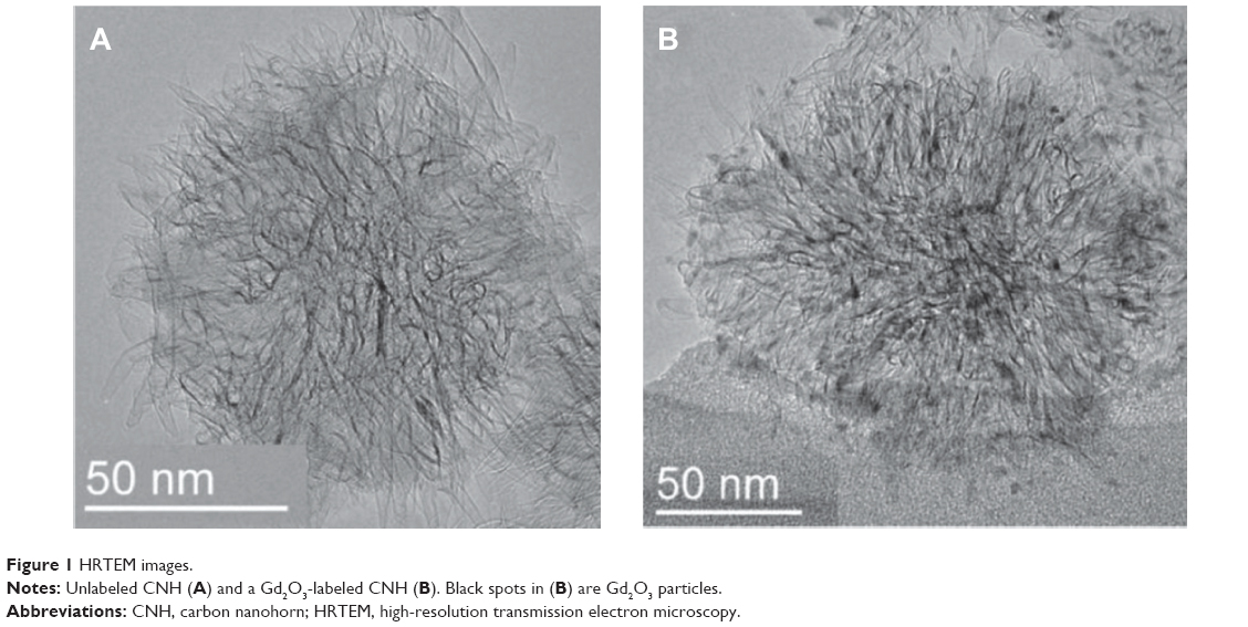 | Figure 1 HRTEM images. |
The dispersion states of CNHs were examined in aqueous solution of PBS. When the DPEG dispersant was used, CNHs were well dispersed in PBS, while without DPEG did not, which was apparent from the photographs of the bottles (Figure 2, insets). This was further examined by measuring the optical absorbance at 800 nm. The absorbance of CNHs dispersed in PBS with the DPEG did not change for 26 hours (Figure 2). However, the absorbance decreased when DPEG was not present (Figure 2). Probably the alkyl chains of DPEG attached to the CNH surface and the PEG moieties helped to keep the CNHs remaining dispersed in the aqueous solutions.24,25 Dynamic light scattering measurements of CNH dispersed in the phosphate buffer (pH 7.4) with DPEG showed that the particle sizes were about 176 nm (not shown), which was a little larger than the CNH size of about 100 nm estimated from TEM images26 (Figure 1). This difference may have been caused by the DPEG coating or by partial agglomeration of the CNHs.
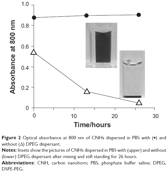 | Figure 2 Optical absorbance at 800 nm of CNHs dispersed in PBS with (•) and without (Δ) DPEG dispersant. |
Biodistribution
The Gd2O3-labeled CNHs dispersed in a 4% glucose aqueous solution with DPEG (0.2 mL; approximately 0.4 mg CNH) were intravenously injected into the tail veins of BALB/c nude mice bearing tumors. The tumors were formed on the backs of mice following the subcutaneous transplantation of SBC-3/VEGF tumor cells (human small cell lung cancer cells). The biodistribution of CNHs at 21 hours after the injection was estimated from the quantities of Gd in each organ measured by inductively coupled plasma atomic emission spectroscopy, as previously reported.12
The CNHs were found primarily in the liver and spleen, followed by the stomach/intestine and kidney (Figure 3A). They also existed in blood, tumor, and skin (Figure 3B). Compared with previous results obtained with CNHs dispersed in glucose without DPEG, the retention of CNHs in the bloodstream increased from <30 minutes (Figure 4A)12 to a period of hours (Figure 4A). This is consistent with other reports, such as the research by Liu et al.8 Probably, DPEG interfered with the uptake of CNHs by phagocytes in the circulating blood. Interestingly, as the quantity of CNHs in the bloodstream decreased from 38% of the injected dose (ID) per gram of tissue (ID/g) at 0.5 hour to almost 1% ID/g at 21 hours, the CNH content in tumor increased from about 1.6% ID/g at 0.5 hour to 3.2% ID/g (Figure 4B), suggesting that a portion of the CNHs circulating in the blood accumulated in tumors.
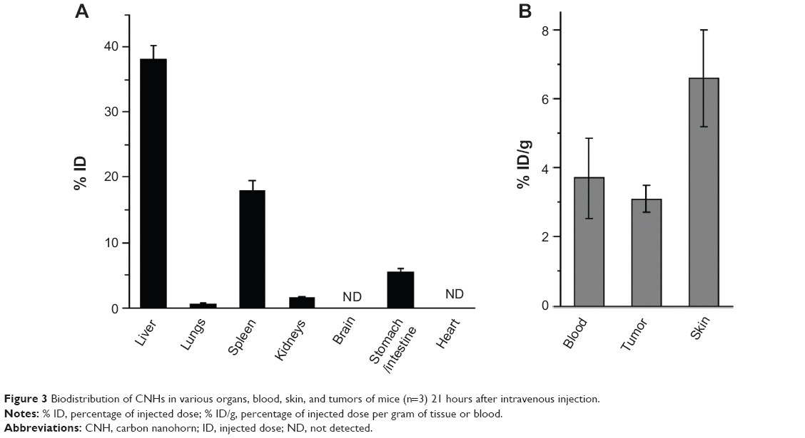 | Figure 3 Biodistribution of CNHs in various organs, blood, skin, and tumors of mice (n=3) 21 hours after intravenous injection. |
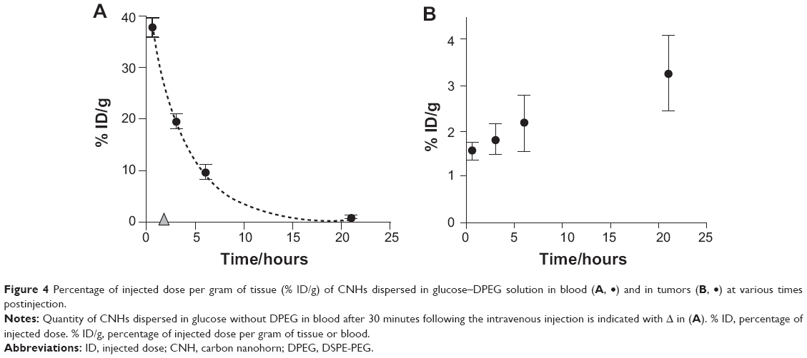 | Figure 4 Percentage of injected dose per gram of tissue (% ID/g) of CNHs dispersed in glucose–DPEG solution in blood (A, •) and in tumors (B, •) at various times postinjection. |
CNHs in tumor tissue
The presence of CNHs at 21 hours after injection was confirmed by histological observation of black spots in tumor tissue stained by nuclear fast red (Figure 5A), where CNHs appeared to be agglomerating in blood vessels or on the vessel walls. Figure 5B shows CNHs present in cells stained with the macrophage antibody anti-Iba-1.
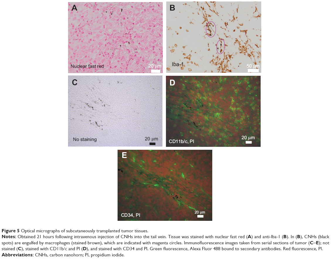 | Figure 5 Optical micrographs of subcutaneously transplanted tumor tissues. |
The endothelial and macrophage cells were further observed with immunofluorescence staining (Figure 5). The CNHs agglomerates were seen in the tissue not stained (Figure 5C). In the nearby sections, the CNHs agglomerates existed in the CD11b/c positive macrophages and CD34 positive endothelial cells, which were found in or near the blood vessels (Figure 5D and E). Here, CD11b/c and CD34 stained cells appear green (Alexa Fluor 488), and the nucleus, red (PI) in Figure 5D and E.
To find the places where the CNHs existed in the tumor tissues more clearly, the tissues were precisely observed with electron microscopy. In the HRTEM observation, CNHs were identified with straight black lines of nanohorn tubule walls running within the CNH aggregates (Figure 1A) or by the black spots of Gd2O3 nanoparticles embedded inside the CNHs (Figure 1B). The CNHs were confirmed to exist within macrophages in tumor blood vessels (Figure 6A–D) and in vascular endothelial cells (Figure 7A–F). In the macrophages, CNHs were localized in membrane-delimited follicles (Figure 6A–D) that were most likely phagosomes (Figure 6C and D). CNHs were also found within micropinocytotic vesicles in endothelial cells (Figure 7C–F). Few CNHs were found outside of the blood vessels in the tumor tissue.
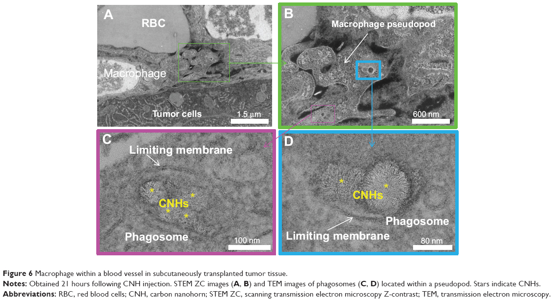 | Figure 6 Macrophage within a blood vessel in subcutaneously transplanted tumor tissue. |
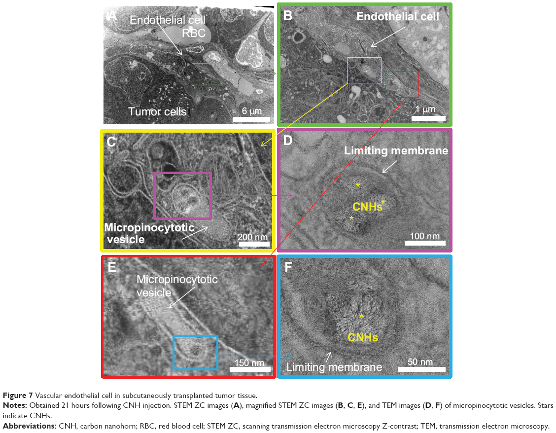 | Figure 7 Vascular endothelial cell in subcutaneously transplanted tumor tissue. |
Interestingly, the CNH agglomerates found in macrophages or endothelial cells of tumors (Figure 6C and D and 7C–F) were relatively small, including two to five CNHs. This means that even though the small CNH-agglomerates reached the subcutaneous tumors, the possibility of extravasation was low. In other words, the enhanced permeability of tumor blood vessels was not highly effective for the passage of agglomerated CNHs.
The CNHs agglomeration size and number in the tumor tissues observed with optical microscopy seemed to be larger than those observed with electron microscopy. This difference is likely to be an artifact caused by that the slices were obtained from different places in the tumor.
CNHs in skin tissue
For comparison, we observed the CNHs in skin from regions where tumor cells had not been transplanted. The skin was slightly darkened by the accumulation of CNHs (not shown), and black CNH agglomerates were found in the dermis and subcutaneous tissues of the skin as apparent from the histology of unstained tissues (Figure 8A and B). Skin accumulation of CNHs is consistent with the previous report of long-circulating single-walled carbon nanotubes;8 however, our results revealed that the distribution was different. Single-walled carbon nanotubes were found only in dermis. The differences could reflect the difference in the size and shape of the CNH and the nanotube. The tissue stained with anti-Iba-1 (Figure 8C and D) showed that CNHs were present in macrophages.
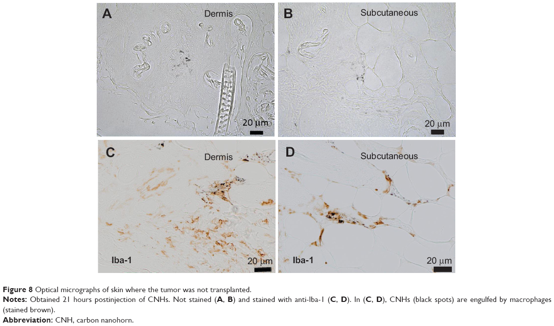 | Figure 8 Optical micrographs of skin where the tumor was not transplanted. |
The skin was further observed with TEM and STEM. Figure 9 shows CNHs in vascular endothelial cells (Figure 9A–C) or macrophages in tissue from the dermis (Figure 9A, D, and E). Figure 10 shows CNHs in the cytosol of macrophages in the subcutaneous tissues. Interestingly, both Figures 9 and 10 show the macrophages present outside of the blood vessels, which differed from the observations in tumor tissue.
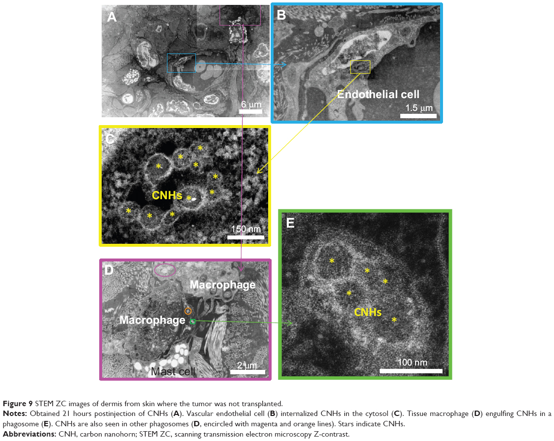 | Figure 9 STEM ZC images of dermis from skin where the tumor was not transplanted. |
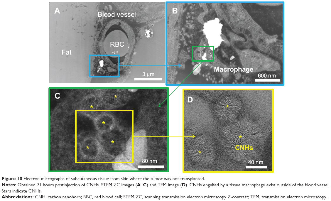 | Figure 10 Electron micrographs of subcutaneous tissue from skin where the tumor was not transplanted. |
Discussion
In general, the blood vessels generated via angiogenesis in tumors have highly permeable vessel walls that permit materials with sizes of 50–200 nm to leave the vessels and reach the tumor cells.18,19 This feature enables liposomes within the optimum size range to deliver antitumor drugs to tumor tissues and cells.18,19 The size of CNHs satisfies this criterion; thus, the same effect is expected. However, in our experiments, DPEG-coated CNHs agglomerated after the injection into mice and were captured by macrophages or vascular endothelial cells inside the tumor blood vessels. In the previous in vitro study, smaller-sized (20–50 nm) CNHs with DPEG coating preclude their uptake by RAW 264.7 macrophage cells,27 thus indicating a possibility that the smaller-sized CNHs with proper surface coating exit the blood vessels in tumor, which remains the challenge.
On the other hand, it is known that the control of macrophage activity in tumors is important for effective tumor treatment.28,29 If the type of tumor macrophages that engulf CNHs were known, then new approaches for the treatment of tumors would be easier to develop.30,31
Since the tumors in this study were formed in the subcutaneous region, we were also curious about the behavior of CNHs in normal skin. We found that the CNHs were captured by macrophages and vascular endothelial cells in the dermis and subcutaneous tissues. Interestingly, in those regions, the CNH-engulfing macrophages were often located outside of the blood vessels. There are two possible mechanisms to account for the movement of CNHs out of the blood vessels. Capillary walls are only one endothelial cell thick; therefore, circulating CNHs trapped by the endothelial cells could be released to the outside of the vessel and captured there by macrophages. Alternatively, macrophages might capture CNHs inside the capillary vessels and then move to the exterior.
Although the immature blood vessels of tumors are highly permeable, they would have not only endothelial cells, but also intima, media, and adventitia tissues. Therefore, the movements of macrophages and CNHs through the vessel walls could be more limited than in the skin capillaries. Finally, it was not the subject of this study, but since the CNHs were observed in the dermis, they may have potential for new therapeutic treatments in the area of dermatology.
Conclusion
CNHs dispersed in aqueous solution of glucose with a phospholipid PEG dispersant were intravenously injected in tail veins of mice bearing subcutaneously transplanted tumors. Histological observation revealed that small agglomerates of two to five CNHs existed within follicles of macrophages and endothelial cells in tumor blood vessels. Small CNH-agglomerates were also found in macrophages and endothelial cells within and, in addition, outside of blood vessels in the dermis and subcutaneous tissues of the normal skin. The extravasation of CNHs was easily found in normal skin, but not so obvious in tumor. This was probably due to their vessel wall structure difference. We conclude that the enhanced permeability of tumor vessels was not sufficient for the transit of CNHs under this study’s conditions.
Acknowledgment
We thank the Japan Science and Technology Agency for supporting this study.
Disclosure
The authors report no conflicts of interest in this work.
References
Robinson JT, Hong G, Liang Y, Zhang B, Yaghi OK, Dai H. In vivo fluorescence imaging in the second near-infrared window with long circulating carbon nanotubes capable of ultrahigh tumor uptake. J Am Chem Soc. 2012;134(25):10664–10669. | ||
Liu Z, Chen K, Davis C, et al. Drug delivery with carbon nanotubes for in vivo cancer treatment. Cancer Res. 2008;68(16):6652–6660. | ||
Yang K, Zhang S, Zhang G, Sun X, Lee ST, Liu Z. Graphene in mice: ultrahigh in vivo tumor uptake and efficient photothermal therapy. Nano Lett. 2010;10(9):3318–3323. | ||
Hong H, Yang K, Zhang Y, et al. In vivo targeting and imaging of tumor vasculature with radiolabeled, antibody-conjugated nanographene. ACS Nano. 2012;6(3):2361–2370. | ||
Chakravarty P, Marches R, Zimmerman NS, et al. Thermal ablation of tumor cells with antibody-functionalized single-walled carbon nanotubes. Proc Natl Acad Sci U S A. 2008;105(25):8697–8702. | ||
Zhang M, Murakami T, Ajima K, et al. Fabrication of ZnPc/protein nanohorns for double photodynamic and hyperthermic cancer phototherapy. Proc Nat Acad Sci U S A. 2008;105(39):14773–14778. | ||
Burke A, Ding X, Singh R, et al. Long-term survival following a single treatment of kidney tumors with multiwalled carbon nanotubes and near-infrared radiation. Proc Natl Acad Sci U S A. 2009;106(31): 12897–12902. | ||
Liu X, Tao H, Yang K, Zhang S, Lee ST, Liu Z. Optimization of surface chemistry on single-walled carbon nanotubes for in vivo photothermal ablation of tumors. Biomaterials. 2011;32(1):144–151. | ||
Cherukuri P, Gannon CJ, Leeuw TK, et al. Mammalian pharmacokinetics of carbon nanotubes using intrinsic near-infrared fluorescence. Proc Natl Acad Sci U S A. 2006;103(50):18882–18886. | ||
Hong G, Lee JC, Robinson JT, et al. Multifunctional in vivo vascular imaging using near-infrared II fluorescence. Nat Med. 2012;18(12): 1841–1846. | ||
Liu Z, Cai W, He L, et al. In vivo biodistribution and highly efficient tumour targeting of carbon nanotubes in mice. Nat Nanotechnol. 2007; 2(1):47–52. | ||
Miyawaki J, Matsumura S, Yuge R, et al. Biodistribution and ultrastructural localization of single-walled carbon nanohorns determined in vivo with embedded Gd2O3 labels. ACS Nano. 2009;3(6):1399–1406. | ||
Qu G, Bai Y, Zhang Y, Jia Q, Zhang W, Yan B. The effect of multiwalled carbon nanotube agglomeration on their accumulation in and damage to organs in mice. Carbon. 2009;47(8):2060–2069. | ||
Zhang S, Yang K, Feng L, Liu Z. In vitro and in vivo behaviors of dextran functionalized graphene. Carbon. 2011;49(12):4040–4049. | ||
Tahara Y, Miyawaki J, Zhang M, et al. Histological assessments for toxicity and functionalization-dependent biodistribution of carbon nanohorns. Nanotechnology. 2011;22(26):265106. | ||
Zhang M, Yamaguchi T, Iijima S, Yudasaka M. Size-dependent biodistribution of carbon nanohorns in vivo. Nanomedicine. 2013;9(5): 657–664. | ||
Singh R, Pantarotto D, Lacerda L, et al. Tissue biodistribution and blood clearance rates of intravenously administered carbon nanotube radiotracers. Proc Natl Acad Sci U S A. 2006;103(9):3357–3362. | ||
Matsumura Y, Maeda H. A new concept for macromolecular therapeutics in cancer chemotherapy: mechanism of tumoritropic accumulation of proteins and the antitumor agent smancs. Cancer Res. 1986;46(12 Pt 1): 6387–6392. | ||
Maeda H. The tumor blood vessel as an ideal target for macromolecular anticancer agents. J Control Release. 1992;19(1–3):315–324. | ||
Smith BR, Kempen P, Bouley D, et al. Shape matters: intravital microscopy reveals surprising geometrical dependence for nanoparticles in tumor models of extravasation. Nano Lett. 2012;12(7):3369–3377. | ||
Iijima S, Yudasaka M, Yamada R, et al. Nano-aggregates of single-walled graphitic carbon nano-horns. Chem Phys Lett. 1999;309(3–4): 165–170. | ||
Azami T, Kasuya D, Yuge R, et al. Large-scale production of single-wall carbon nanohorns with high purity. The Journal of Physical Chemistry C. 2008;112(5):1330–1334. | ||
Yuge R, Ichihashi T, Miyawaki J, Yoshitake T, Iijima S, Yudasaka M. Hidden caves in an aggregate of single-wall carbon nanohorns found by using Gd2O3 probes. The Journal of Physical Chemistry C. 2009;113(7): 2741-2744. | ||
Hadidi N, Kobarfard F, Nafissi-Varcheh N, Aboofazeli R. Optimization of single-walled carbon nanotube solubility by noncovalent PEGylation using experimental design methods. Int J Nanomedicine. 2011;6: 737–746. | ||
Yang M, Wada M, Zhang M, et al. A high poly(ethylene glycol) density on graphene nanomaterials reduces the detachment of lipid-poly(ethylene glycol) and macrophage uptake. Acta Biomater. 2013;9(1):4744–4753. | ||
Azami T, Kasuya D, Yoshitake T, et al. Production of small single-wall carbon nanohorns by CO2 laser ablation of graphite in Ne-gas atmosphere. Carbon. 2007;45(6):1364–1367. | ||
Zhang M, Zhou X, Iijima S, Yudasaka M. Small-sized carbon nanohorns enabling cellular uptake control. Small. 2012;8(16):2524–2531. | ||
De Palma M, Lewis CE. Cancer: Macrophages limit chemotherapy. Nature. 2011;472(7343):303–304. | ||
Wynn TA, Chawla A, Pollard JW. Macrophage biology in development, homeostasis and disease. Nature. 2013;496(7446):445–455. | ||
Shime H, Matsumoto M, Oshiumi H, et al. Toll-like receptor 3 signaling converts tumor-supporting myeloid cells to tumoricidal effectors. Proc Natl Acad Sci U S A. 2012;109(6):2066–2071. | ||
Cieslewicz M, Tang J, Yu JL, et al. Targeted delivery of proapoptotic peptides to tumor-associated macrophages improves survival. Proc Natl Acad Sci U S A. 2013;110(40):15919–15924. |
 © 2014 The Author(s). This work is published and licensed by Dove Medical Press Limited. The full terms of this license are available at https://www.dovepress.com/terms.php and incorporate the Creative Commons Attribution - Non Commercial (unported, v3.0) License.
By accessing the work you hereby accept the Terms. Non-commercial uses of the work are permitted without any further permission from Dove Medical Press Limited, provided the work is properly attributed. For permission for commercial use of this work, please see paragraphs 4.2 and 5 of our Terms.
© 2014 The Author(s). This work is published and licensed by Dove Medical Press Limited. The full terms of this license are available at https://www.dovepress.com/terms.php and incorporate the Creative Commons Attribution - Non Commercial (unported, v3.0) License.
By accessing the work you hereby accept the Terms. Non-commercial uses of the work are permitted without any further permission from Dove Medical Press Limited, provided the work is properly attributed. For permission for commercial use of this work, please see paragraphs 4.2 and 5 of our Terms.