")
Back to Journals » International Journal of Nanomedicine » Volume 10 » Issue 1
Thickness-controllable electrospun fibers promote tubular structure formation by endothelial progenitor cells
Authors Hong JK, Bang JY, Xu G, Lee J, Kim Y, Lee H, Kim HS, Kwon S
Received 22 August 2014
Accepted for publication 16 October 2014
Published 10 February 2015 Volume 2015:10(1) Pages 1189—1200
DOI https://doi.org/10.2147/IJN.S73096
Checked for plagiarism Yes
Review by Single anonymous peer review
Peer reviewer comments 3
Editor who approved publication: Dr Thomas Webster
Jong Kyu Hong,1,2 Ju Yup Bang,3 Guan Xu,4 Jun-Hee Lee,1 Yeon-Ju Kim,1 Ho-Jun Lee,5 Han Seong Kim,3 Sang-Mo Kwon1,2,6
1Laboratory for Vascular Medicine and Stem Cell Biology, Medical Research Institute, Department of Physiology, School of Medicine, Pusan National University, Yangsan, South Korea; 2Conversence Stem Cell Research Center, Medical Research Institute, School of Medicine, Pusan National University, Yangsan, South Korea; 3Department of Organic Material Science, Pusan National University, Geumjeong-gu, Busan, South Korea; 4Department of Radiology, School of Medicine, University of Michigan, Ann Arbor, MI, USA; 5Department of Electrical Engineering, Pusan National University, Geumjeong-gu, Busan, South Korea; 6Immunoregulatory Therapeutics Group in Brain Busan 21 Project, Department of Physiology, Pusan National University School of Medicine, Yangsan, South Korea
Abstract: Controlling the thickness of an electrospun nanofibrous scaffold by altering its pore size has been shown to regulate cell behaviors such as cell infiltration into a three-dimensional (3D) scaffold. This is of great importance when manufacturing tissue-engineering scaffolds using an electrospinning process. In this study, we report the development of a novel process whereby additional aluminum foil layers were applied to the accumulated electrospun fibers of an existing aluminum foil collector, effectively reducing the incidence of charge buildup. Using this process, we fabricated an electrospun scaffold with a large pore (pore size >40 µm) while simultaneously controlling the thickness. We demonstrate that the large pore size triggered rapid infiltration (160 µm in 4 hours of cell culture) of individual endothelial progenitor cells (EPCs) and rapid cell colonization after seeding EPC spheroids. We confirmed that the 3D, but not two-dimensional, scaffold structures regulated tubular structure formation by the EPCs. Thus, incorporation of stem cells into a highly porous 3D scaffold with tunable thickness has implications for the regeneration of vascularized thick tissues and cardiac patch development.
Keywords: electrospinning, nanofibrous scaffold, tunable thickness, vascularization, stem cell
Introduction
Recently, electrospinning has gained considerable attention in the field of tissue engineering.1–6 Biomimetic, nonwoven, nanofibrous scaffolds composed of large networks of interconnected fibers and pores may be fabricated via electrospinning.7 Electrospun nanofibrous scaffolds of synthetic and natural polymers, such as polycaprolactone (PCL) and gelatin,8 have been fabricated to regenerate organs or tissues, including bone,9 cartilage,10 skin,11 neurons,12 and blood vessels.13 A major limitation of traditional electrospun fibers is their small pore size, which restricts cell growth to the surface of the scaffold without any cell infiltration. Seeded cells have been shown to migrate, proliferate, and colonize on the superficial layer of these scaffolds in a manner resembling two-dimensional (2D) cell sheets.7 Blakeney et al7 previously designed a collector with an open space to fabricate a cotton-ball-like electrospun scaffold (20 μm pore size), which was shown to support cell infiltration after 7 days of cell culture. A recent report describing modifications to the void space of the collector demonstrated progress in enlarging the pore size of electrospun scaffold; however, it was shown that controlling the thickness of electrospun fibers is another limitation that must be addressed for electrospun scaffolds. In particular, charge buildup on the collector was shown to hinder the ability to tune the thickness of three-dimensional (3D) electrospun scaffolds, which would be advantageous for tissue engineering applications.14 In addition to adequate pore size, a vascular network within 3D scaffolds is essential because sufficient in vitro vascularization is required for the functioning of the regenerated thick and dense tissues and organs when they are implanted into patients. Thus, methods for neovascularization in engineered 3D scaffolds have been widely studied in the field of tissue engineering15–18 to interconnect pre-vascularized forms with blood vessels in the host tissue during implantation.19 These approaches often use endothelial progenitor cells (EPCs), a population of rare cells extracted from the blood, which have the ability to differentiate into endothelial cells that form the lining of blood vessels.20–23
In this study, we investigated a novel electrospinning process where the incidence of charge buildup on the collector was reduced by stacking aluminum foils on the electrospun scaffold after following each electrospinning step. This allowed us to effectively reduce the charge buildup on the collector. With this approach, we were able to tune the thickness of the large-pored electrospun scaffolds that were formed. Analysis of the electrospun scaffold with in vitro cell culture confirmed rapid infiltration, proliferation, and colonization of EPCs throughout the 3D scaffold comprising highly porous electrospun fibers of controlled thickness. Finally, we examined the formation of tubular structures by EPCs on the 3D scaffolds in response to the pore size of electrospun fibers during in vitro cell colonization.
Materials and methods
Material fabrication
Fabrication of a single layer of highly porous electrospun scaffold
PCL (average molecular weight: 80,000; Sigma-Aldrich Co., St Louis, MO, USA) was dissolved at 1.5 g/mL in a solvent mixture of 9:1 (v/v) chloroform (Junsei, Tokyo, Japan), and methanol (Duksan, Gyeonggi-do, South Korea). The electrospinning apparatus consisted of a syringe pump (KD Scientific, Holliston, MA, USA), a 10-mL syringe (Becton Dickinson, Franklin Lakes, NY, USA), a needle tip (23G; Becton Dickinson), a high-voltage power supply (KSC Inc., Seoul, South Korea), an earth grounder, and a collector (Figure 1A). To produce the highly porous 3D electrospun scaffold, a novel collector with a void (0.5 cm diameter and 0.95 cm depth) was designed on a hexagonal polystyrene weighing dish (0.44×0.95 cm; Eagle Inc., Hodgenville, KY, USA) wrapped with an aluminum foil (16 μm thick).24 A traditional collector with the same geometry as the novel collector, but without the void space, was also wrapped in aluminum foil for producing the 2D scaffold. Scaffolds (3D and 2D) were fabricated at the rate of 0.2 mL/h at 10 kV. The distance between the collector and needle tip was 8 cm, and the deposited volume of the solution was 0.2 mL.
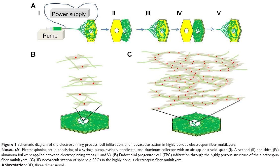 | Figure 1 Schematic diagram of the electrospinning process, cell infiltration, and neovascularization in highly porous electrospun fiber multilayers. |
Fabrication of highly porous electrospun scaffold with tunable thickness
After each of the three electrospinning steps, a layer of aluminum foil with a void of 0.5 cm was applied to the existing electrospun fibers on the collector. Consequently, three layers of highly porous electrospun scaffold were fabricated. Although the diameter of the highly porous region in this study was 0.5 cm, this region could be expanded by enlarging the diameter of the hole to as large as approximately 10 cm.8
Scaffold characterization
Scanning electron microscopy imaging
Fabricated 2D and 3D scaffolds were analyzed using a SUPRA25 electron microscope (Carl Zeiss, Jena, Germany) at an acceleration voltage of 10 kV. Samples were attached to a silicon wafer by using carbon tape (3M, St Paul, MN, USA) and sputter-coated with gold for 1 minute prior to scanning electron microscopy (SEM) analysis.
Confocal imaging
The 3D scaffolds were then imaged using an Olympus FV1000 confocal microscope (Olympus Corporation, Tokyo, Japan) and analyzed using the FV10-ASW software (Olympus).
Microstructure characterization
The mean diameters of samples were measured on SEM images using iSolution Lite (IMT i-Solution Inc., Burlington, ON, Canada) for length measurements. For the measurement of fiber diameter, a total of 100 measurements were made on ten different SEM images of each sample, each representing a random field of view for different electrospun fiber configuration. The software was also used to measure the mean pore size of samples using SEM images and total of 100 measurements were made on ten different SEM images of each sample. The mean thickness of samples were measured using an LV- 10 microscope (Nikon, Tokyo, Japan) moving in a vertical direction. For the measurement of mean thickness, a total of 100 measurements were made on ten different samples. Each thickness was measured by measuring the distance between the top and bottom fibers at a random point of different electrospun fiber configuration.
Computational simulation
The electrical potential drop near the collector was simulated using COMSOL 4.5 Multiphysics (COMSOL, Burlington, MA, USA).25 The basic equation used in the simulation was the Laplacian equation:
∇2ϕ=0 |
where ϕ is the electric potential. All assumptions and boundary conditions were based on the experimental electrospinning setup. The relative permittivity was set to 1, and the relative permittivity of the hexagonal polymer collector was set to 2. Grounded aluminum foil was set to zero potential (ground), and the needle surface was set to 10 kV. All the outer boundaries were set to zero charge because no actual dielectric interfaces existed at these boundaries.
Cell culture
Cell isolation and culture
EPCs were isolated from human umbilical cord blood26,27 obtained from donors at Pusan National University Hospital (PNUH, Yangsan, South Korea). All procedures were as described in a protocol approved by the Institutional Review Board of PNUH (Approval No. PNUH-2012-19). EPCs were cultured on dishes coated with 1% gelatin in endothelial basal medium 2 (Lonza, Walkersville, MD, USA) supplemented with 5% fetal bovine serum (FBS), human vascular endothelial growth factor, human basic fibroblast growth factor, human epidermal growth factor, human insulin-like growth factor 1, ascorbic acid, and GA-1000 endothelial cell growth medium 2 (EGM-2; Lonza). After 4 days, nonadherent cells were discarded and fresh culture medium was added. The medium was changed daily for 7 days and then every 2 days until the first passage. EPC colonies appeared 14–21 days after the initial isolation. EPCs were used at passages 3–5 for all experiments after flow cytometry analysis (Figure S1), which was used to confirm that the cells used in this study were EPCs. The cells were still healthy and continued to proliferate at passage 6 and above.26,27
Spheroid Culture of EPCs
To generate spheroids, EPCs (6×10⁵ cells/mL) were placed in ultra-low attachment dishes (Corning, NY, USA) and shaken at 60 rpm for 1 day.
Cell infiltration study
After the samples were treated with ultraviolet for 4 hours, 70% ethanol for 4 hours, and EGM-2 media containing 5% FBS, 100 μL of EPC suspension (1×10⁶ cells/mL) was seeded on the electrospun scaffold. After 4 hours of culture, cells in the scaffold were fixed using 3.7% formaldehyde and stained using 2 mL of 4′,6-diamidino-2-phenylindole (DAPI; 30 nmol; Invitrogen [Thermo Fisher Scientific], Waltham, MA, USA). The distribution of DAPI-stained EPCs on the scaffold was confirmed using confocal microscopy. The EPC morphology was examined using SEM after EPCs on the 2D or 3D scaffolds were fixed using 3.7% formaldehyde and dried through an ethanol gradient.
Cell proliferation study
EPCs (6×10⁶ cells/mL; ~20 μm in diameter) were seeded on the electrospun scaffold. After 3 days of cell culture, EPCs in the scaffold were fixed using 3.7% formaldehyde and stained using 2 mL of DAPI (30 nmol) for cell nuclei and Alexa Fluor 488 phalloidin (0.661 M; Invitrogen) for cytoskeletal actin. Also, Ki-67 (1:500; Santa Cruz Biotechnology, Inc, Dallas, TX, USA), proliferating cell nuclear antigen (1:500; PCNA; Santa Cruz Biotechnology), and fluorescent (594 nm) secondary antibodies (at a dilution of 1:2,000; Santa Cruz Biotechnology) against the rabbit primary antibodies were used. The cells were examined using confocal microscopy.
Cell colonization study
Three milliliters of EPC spheroids (6×10⁶ cells/mL; ~150 μm in diameter) was seeded on the electrospun scaffolds, and the cells were monitored using light microscopy during the cell culture. After 3 days of cell culture, the aluminum foil frames were removed from the scaffold using scissors. The fiber structure was mechanically stable because of the colonized cells around the fibers, which formed a hybrid structure of cells and fibers inside the scaffold. Thus, the 3D scaffold structure remained intact without the fibers collapsing during the 3D cell culture, even after the aluminum foil frames were removed from the scaffold.24 As previously described,24 the colonized EPCs on the 3D scaffold were fixed using 3.7% formaldehyde, dried through an ethanol gradient, embedded in paraffin, stained with hematoxylin and eosin (H&E), and examined using a MIRAX MIDI slide scanner (Carl Zeiss, Jena, Germany). Also, cell morphology was confirmed using SEM after EPCs on the 2D or 3D scaffolds were fixed using 3.7% formaldehyde and dried through an ethanol gradient.
Statistical analysis
Statistical analyses were performed using single-factor analysis of variance. A value of P≤0.05 was considered statistically significant.
Results
Novel Process to control thickness and scaffold morphology
To control the thickness of highly porous electrospun fibers, aluminum foils with a void space were applied to existing electrospun fibers on a novel collector (Figure 1A). The average thickness of the electrospun scaffolds increased from 93.18 μm to 619.22 μm when one and three layers of aluminum foil were used, respectively (P<0.05). The average pore size was 85.75 μm and 48.21 μm for one and three layers of aluminum foil, respectively. These pores were significantly larger than those generated using the traditional 2D scaffold (average pore size, <7 μm; P<0.05). The average diameter of single fibers generated using the collector without a void was approximately 4 μm. A similar diameter was attained when one and three layers of aluminum foil were used (P>0.05) (Figure 2 and Table 1).
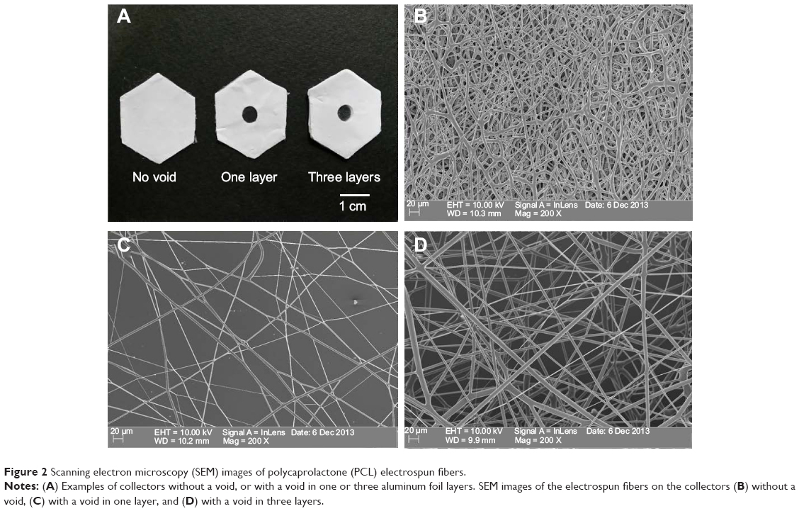 | Figure 2 Scanning electron microscopy (SEM) images of polycaprolactone (PCL) electrospun fibers. |
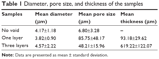 | Table 1 Diameter, pore size, and thickness of the samples |
Computational simulation study
COMSOL simulation showed that equipotential lines in the electric fields on the collector with a void space were the same before and after stacking the aluminum foil layers because the distance between the aluminum foil layers on the collector (hundreds of micrometers) was much smaller than that between the needle tip and the collector (tens of centimeters) (Figure 3A–C). These similar equipotential lines regulated the collection of similar fiber structures inside the voids (fiber diameter and pore size) when the aluminum foil layers were stacked.
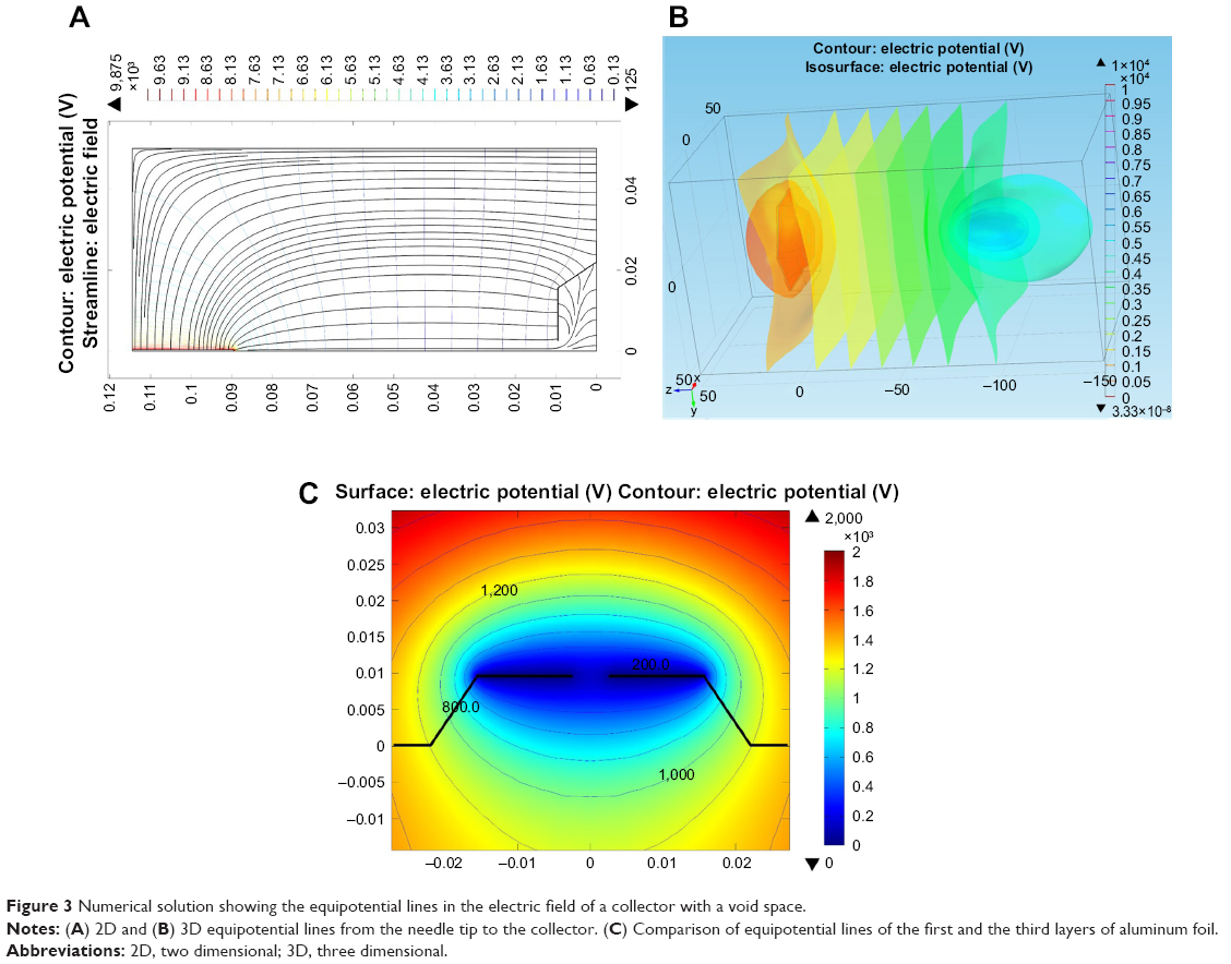 | Figure 3 Numerical solution showing the equipotential lines in the electric field of a collector with a void space. |
Cell attachment, filtration, and proliferation
Cells were seeded on the top surface of the three-layered electrospun scaffold and cultured for 4 hours before single-cell morphology was examined using confocal microscopy and SEM. Single cells were distributed within a 160-μm distance from the top surface of the electrospun scaffold after 4 hours of cell culture (Figure 4A). EPCs were found in each layer of the electrospun fiber scaffold (Figure 4A-1 to A-4). The majority of the EPCs maintained their spheroid shape (Figure 4A-5 to A-7), but some individual EPCs started to spread between fibers (Figure 4A-8). EPCs on the traditional 2D scaffold became spheroidal (Figure 4B-1) or began to spread out on the 2D scaffold surface (Figure 4B-2). Although a few cells were trapped between the superficial fibers (Figure 4B-3), EPCs were observed only at the top layer of 2D scaffold (Figure 4B). After 3 days of cell culture, spheroids consisting of two or three EPCs were formed and attached on the fibers. Throughout the scaffold (Figure 5B-1 to B-3), proliferating EPCs were observed inside the spheroids (Figure 4A-1 to A-6).
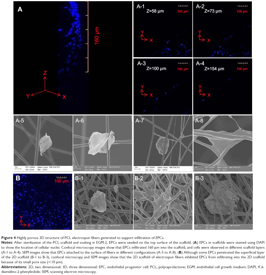 | Figure 4 Highly porous 3D structure of PCL electrospun fibers generated to support infiltration of EPCs. |
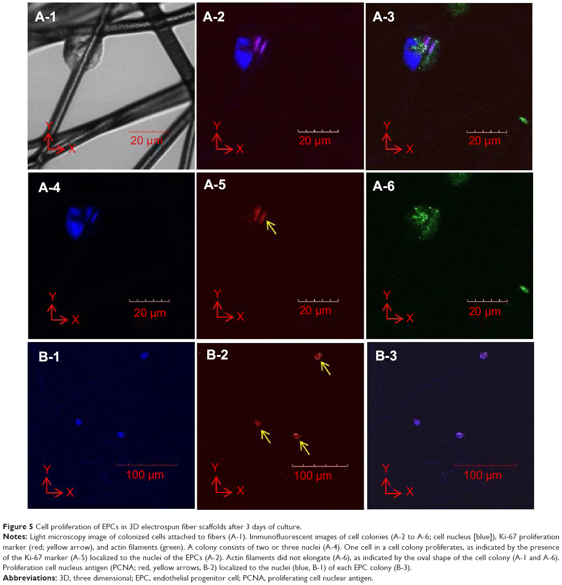 | Figure 5 Cell proliferation of EPCs in 3D electrospun fiber scaffolds after 3 days of culture. |
Cell colonization and neovascularization in 3D electrospun scaffolds
To reduce the time required to achieve EPC colonization inside the 3D scaffold, EPC spheroids (150 μm in diameter) were placed on a shaker for 24 hours. EPC spheroids were then seeded onto the highly porous fibers of the 3D scaffold and cultured for 3 days. EPCs were distributed throughout the depth of the electrospun fiber scaffold (Figure 6A-1). EPC spheroids were proliferating (Figure 6A-2 and A-3), filling the gaps between the electrospun fibers. As shown in Figure 6A-1 and A-3, EPCs colonized the entire 3D scaffold. EPCs that colonized on the fibers of the 3D scaffold formed tubular structures with diameters varying between 2 μm and 50 μm (Figure 6A-4 and A-5). In contrast, no tubular structures were formed on the 2D scaffold. Rather, EPCs spread outward on the top surface when EPC spheroids were seeded onto 2D scaffolds and cultured for 3 days (Figure 6B-1 and B-2).
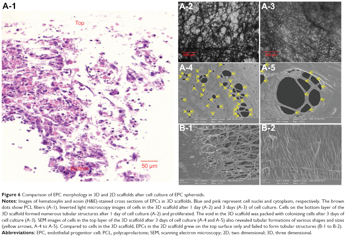 | Figure 6 Comparison of EPC morphology in 3D and 2D scaffolds after cell culture of EPC spheroids. |
Discussion
Tuning the thickness of interconnected electrospun fibers with large pore size using a novel process
Electrospinning is a very versatile and economical method to generate microenvironments mimicking the extracellular matrix (ECM), which can be used for tissue regeneration. However, methods to control the thickness of highly porous electrospun scaffolds are limited because electrospun fibers with a large pore size8,24 and controlled scaffold thickness cannot be simultaneously collected with traditional flat collectors.28 In this study, we simultaneously engineered the thickness and the pore size of electrospun fibers by designing a novel collector configuration. Aluminum foils were stacked on the existing electrospun fibers between sequential electrospinning steps, which significantly reduced the charge buildup by grounding the aluminum foil.29 This enhanced the effective driving force, thus permitting the collection of thickness-tunable scaffolds with an intact, highly porous fiber structure resulting from the void space in the aluminum foil.25 In addition, electrospun fibers were interconnected with the existing fibers through the voids in the aluminum foil layers because the solvent did not fully evaporate inside or on the surface of the electrospun fiber layers. Thus, these highly porous and interconnected electrospun fibers accumulated through the voids within the stacked aluminum foil of the collector. With the introduction of an aluminum foil to the configuration, an interconnected and highly porous electrospun scaffold with tunable thickness was created, indicating that the design and configuration of electrospinning collectors affected the fabricated scaffold structure (pore size, thickness, and interconnectivity). As shown in this study, electrospinning has been used to design advanced PCL structures for tissue engineering, but electrospinning has also reportedly been combined with rapid prototyping techniques, such as fiber extrusion.30 In addition, many research groups have reported the modification of PCL and PCL-based scaffolds and substrates. For example, a method consisting of 3D fiber deposition and aminolysis, followed by peptide coupling, resulted in the fabrication of 3D PCL scaffolds with RGD (arginylglycylaspartic acid) surface peptides that exhibited controlled morphology as well as macro, micro, and nano-mechanical properties.31 Extruded PCL scaffolds were also plasma-treated with a C2H4/N2 deposition, followed by H2 posttreatment, to coat the surface of 3D structures with a nitrogen-rich film containing groups to enhance the scaffold’s hydrophilicity and cell affinity.32 Furthermore, iron-doped hydroxyapatite nanoparticles were embedded in a PCL matrix to develop fully biodegradable nanocomposite 2D substrates for bone tissue engineering.33 Therefore, the combination of structural and functional modifications for PCL scaffolds/substrates can enrich the properties of PCL-based 3D scaffolds for cell culture studies and tissue/organ regeneration.
Regulating the structure of the scaffold structure to control cell behavior
The structure of electrospun scaffolds is critical for the regulation of cell behavior, including cell infiltration, proliferation, colonization, and neovascularization. In particular, the effect of the pore size of electrospun fibers on these cell processes had not been fully evaluated previously because the pore size of the fibers could not be engineered. In this study, EPCs infiltrated 160 μm from the top of the scaffold through the interconnected and highly porous structure of electrospun fibers after only 4 hours of cell culture. In a previous study, cells infiltrated 100 μm through electrospun fibers (the pore size of the scaffold, <20 μm) after 7 days of cell culture.7 Thus, in comparison, rapid cell infiltration (<100 μm in 4 hours of cell culture) was observed with our scaffold, as indicated by a cell infiltration time shortened by 40-fold and significantly enhanced cell infiltration due to the highly porous structure of the electrospun fibers (pore size >45 μm). It is also clear that the majority of the cells were attached on the surface of the 2D electrospun mesh. However, the majority of cells passed through the pores of the 3D scaffolds because the scaffold pore size (pore size >45 μm) is larger than the size of the EPCs (about 20 μm), although we soaked the 3D scaffold in media containing FBS before cell seeding to enhance cell attachment.34 Ironically, because of the large scaffold pore size, the cell seeding issue was negligible because the EPC spheroids (about 150 μm in diameter) are larger than the pores of the fibers.
When the EPC spheroids were seeded onto the 3D scaffold, the majority of the spheroids were entrapped by the fibers of the 3D scaffold. Thus, instead of seeding EPCs on the top surface of the scaffold, we decided to seed the EPC spheroids on the 3D scaffold. This was done to not only overcome the cell-seeding issue but also reduce the time required for cell colonization because two or three EPCs were shown to aggregate and form spheroids which attached to the fibers and proliferated inside the spheroid. Within 3 days of spheroid seeding, EPC colonization was observed. The structure of the 3D scaffold accumulated many EPC spheroids in a short period of time because the colonized cells became trapped between the fibers, aggregated, and colonized the scaffold. Thus, the EPCs colonizing the 3D scaffold were intact and stable even after removing the aluminum foil.24 Furthermore, colonized EPCs formed tubular structures in the absence of any biomaterials including Matrigel, which is known to support tubule formation in 2D cultures.35 In contrast, no vascularization was observed on traditional 2D scaffolds composed of PCL electrospun fibers, suggesting that only the pore size of the electrospun fibers regulated neovascularization of EPCs colonizing the 3D scaffolds. In summary, the scaffold structure (interconnectivity, porousness, and thickness) was shown to regulate cell behavior (rate of cell infiltration, cell proliferation, cell colonization, and neovascularization). Therefore, incorporation of various stem cells into interconnected, highly porous 3D electrospun scaffolds of tunable thickness, made from different biomaterials, could be useful for promoting the regeneration of vascularized full-thickness tissues and organs such as cardiac patches or other tissue types.
Conclusion
We demonstrated that the thickness of highly porous electrospun scaffolds could be controlled by stacking aluminum foils with void spaces on an electrospinning collector because the aluminum foils were grounded, thereby dramatically reducing the incidence of charge buildup. The increased pore size of the electrospun scaffolds permitted rapid cell infiltration and colonization, and the 3D structure of the electrospun fibers allowed the EPCs to form tubular structures. Consequently, the structure (pore size) of the 3D scaffold regulated the EPC behavior, including cell infiltration, proliferation, colonization, and neovascularization. These findings have implications for the generation of vascularized tissues and regeneration of thick tissues.
Acknowledgments
This research was supported financially by the National Research Foundation funded by the Korean government (MEST; 2010-0020260, NRF-2012R1A2A2A01045085, and NRF-2014R1A1A2008392) and a grant from the Korean Health Technology R&D Project, Ministry of Health and Welfare, Republic of Korea (A120247).
Disclosure
The authors declare no conflicts of interest in this work.
References
Grey CP, Newton ST, Bowlin GL, Haas TW, Simpson DG. Gradient fiber electrospinning of layered scaffolds using controlled transitions in fiber diameter. Biomaterials. 2013;34(21):4993–5006. | ||
Ajalloueian F, Lim ML, Lemon G, et al. Biomechanical and biocompatibility characteristics of electrospun polymeric tracheal scaffolds. Biomaterials. 2014;35(20):5307–5315. | ||
Chen X, Ergun A, Gevgilili H, Ozkan S, Kalyon DM, Wang H. Shell-core bi-layered scaffolds for engineering of vascularized osteon-like structures. Biomaterials. 2013;34(33):8203–8212. | ||
Dargaville BL, Vaquette C, Rasoul F, Cooper-White JJ, Campbell JH, Whittaker AK. Electrospinning and crosslinking of low-molecular-weight poly(trimethylene carbonate-co-(l)-lactide) as an elastomeric scaffold for vascular engineering. Acta Biomater. 2013;9(6):6885–6897. | ||
Ortega I, Ryan AJ, Deshpande P, MacNeil S, Claeyssens F. Combined microfabrication and electrospinning to produce 3-D architectures for corneal repair. Acta Biomater. 2013;9(3):5511–5520. | ||
Warnke PH, Alamein M, Skabo S, et al. Primordium of an artificial Bruch’s membrane made of nanofibers for engineering of retinal pigment epithelium cell monolayers. Acta Biomater. 2013;9(12):9414–9422. | ||
Blakeney BA, Tambralli A, Anderson JM, et al. Cell infiltration and growth in a low density, uncompressed three-dimensional electrospun nanofibrous scaffold. Biomaterials. 2011;32(6):1583–1590. | ||
Hong JK, Madihally SV. Next generation of electrosprayed fibers for tissue regeneration. Tissue Eng Part B Rev. 2011;17(2):125–142. | ||
Tutak W, Sarkar S, Lin-Gibson S, et al. The support of bone marrow stromal cell differentiation by airbrushed nanofiber scaffolds. Biomaterials. 2013;34(10):2389–2398. | ||
Li WJ, Tuli R, Okafor C, et al. A three-dimensional nanofibrous scaffold for cartilage tissue engineering using human mesenchymal stem cells. Biomaterials. 2005;26(6):599–609. | ||
Kumbar SG, Nukavarapu SP, James R, Nair LS, Laurencin CT. Electrospun poly(lactic acid-co-glycolic acid) scaffolds for skin tissue engineering. Biomaterials. 2008;29(30):4100–4107. | ||
Binan L, Tendey C, De Crescenzo G, El Ayoubi R, Ajji A, Jolicoeur M. Differentiation of neuronal stem cells into motor neurons using electrospun poly-l-lactic acid/gelatin scaffold. Biomaterials. 2014;35(2):664–674. | ||
Rayatpisheh S, Heath DE, Shakouri A, Rujitanaroj PO, Chew SY, Chan-Park MB. Combining cell sheet technology and electrospun scaffolding for engineered tubular, aligned, and contractile blood vessels. Biomaterials. 2014;35(9):2713–2719. | ||
Lee SJ, Oh SH, Liu J, Soker S, Atala A, Yoo JJ. The use of thermal treatments to enhance the mechanical properties of electrospun poly(ε-caprolactone) scaffolds. Biomaterials. 2008;29(10):1422–1430. | ||
Zhang Z, Ito WD, Hopfner U, et al. The role of single cell derived vascular resident endothelial progenitor cells in the enhancement of vascularization in scaffold-based skin regeneration. Biomaterials. 2011;32(17):4109–4117. | ||
Criswell TL, Corona BT, Wang Z, et al. The role of endothelial cells in myofiber differentiation and the vascularization and innervation of bioengineered muscle tissue in vivo. Biomaterials. 2013;34(1):140–149. | ||
McNeill B, Tiwari-Pandey R, Ruel M, Suuronen EJ. 4 – Biomaterials for enhancing endothelial progenitor cell (EPC) therapy for cardiac regeneration. In: Li R-K, Weisel RD, editors. Cardiac Regeneration and Repair. Cambridge: Woodhead Publishing; 2014:82–109. | ||
Berry SM, Warren SP, Hilgart DA, et al. Endothelial cell scaffolds generated by 3D direct writing of biodegradable polymer microfibers. Biomaterials. 2011;32(7):1872–1879. | ||
Rivron NC, Liu JJ, Rouwkema J, de Boer J, van Blitterswijk CA. Engineering vascularised tissues in vitro. Eur Cell Mater. 2008;15:27–40. | ||
Kwon SM, Lee YK, Yokoyama A, et al. Differential activity of bone marrow hematopoietic stem cell subpopulations for EPC development and ischemic neovascularization. J Mol Cell Cardiol. 2011;51(3):308–317. | ||
Kwon SM, Suzuki T, Kawamoto A, et al. Pivotal role of lnk adaptor protein in endothelial progenitor cell biology for vascular regeneration. Circ Res. 2009;104(8):969–977. | ||
Yoo SY, Kwon SM. Angiogenesis and its therapeutic opportunities. Mediators Inflamm. 2013;2013:127170. | ||
Zhang Z, Ito WD, Hopfner U, et al. The role of single cell derived vascular resident endothelial progenitor cells in the enhancement of vascularization in scaffold-based skin regeneration. Biomaterials. 2011;32(17):4109–4117. | ||
Hong JK, Madihally SV. Three-dimensional scaffold of electrosprayed fibers with large pore size for tissue regeneration. Acta Biomater. 2010;6(12):4734–4742. | ||
Hong JK, Xu G, Piao D, Madihally SV. Analysis of void shape and size in the collector plate and polycaprolactone molecular weight on electrospun scaffold pore size. J Appl Polym Sci. 2013;128(3):1583–1591. | ||
Kamei N, Kwon SM, Ishikawa M, et al. Endothelial progenitor cells promote astrogliosis following spinal cord injury through Jagged1-dependent Notch signaling. J Neurotrauma. 2012;29(9):1758–1769. | ||
Lee JH, Lee SH, Yoo SY, Asahara T, Kwon SM. CD34 hybrid cells promote endothelial colony-forming cell bioactivity and therapeutic potential for ischemic diseases. Arterioscler Thromb Vasc Biol. 2013;33(7):1622–1634. | ||
Vaquette C, Cooper-White J. A simple method for fabricating 3-D multilayered composite scaffolds. Acta Biomater. 2013;9(1):4599–4608. | ||
Vaquette C, Cooper-White J. The use of an electrostatic lens to enhance the efficiency of the electrospinning process. Cell Tissue Res. 2012;347(3):815–826. | ||
Gomez E, Dias J, Amora U, Rodríguez CA, Gloria A, Bártolo P. Morphological and mechanical evaluation of hybrid scaffolds for bone regeneration. Adv Mater Res. 2013;749:429–432. | ||
Gloria A, Causa F, Russo T, et al. Three-dimensional poly(ε-caprolactone) bioactive scaffolds with controlled structural and surface properties. Biomacromolecules. 2012;13(11):3510–3521. | ||
Domingos M, Intranuovo F, Gloria A, et al. Improved osteoblast cell affinity on plasma-modified 3-D extruded PCL scaffolds. Acta Biomater. 2013;9(4):5997–6005. | ||
Gloria A, Russo T, D’Amora U, et al. Magnetic poly(epsilon-caprolactone)/iron-doped hydroxyapatite nanocomposite substrates for advanced bone tissue engineering. J R Soc Interface. 2013;10(80):20120833. | ||
Blakeney BA, Tambralli A, Anderson JM, et al. Cell infiltration and growth in a low density, uncompressed three-dimensional electrospun nanofibrous scaffold. Biomaterials. 2011;32(6):1583–1590. | ||
Kinsella JL, Grant DS, Weeks BS, Kleinman HK. Protein kinase C regulates endothelial cell tube formation on basement membrane matrix, Matrigel. Exp Cell Res. 1992;199(1):56–62. |
Supplementary material
Flow cytometry analysis
Flow cytometry analysis was performed to characterize the surface markers of the endothelial progenitor cells (EPCs), as previously described.1,2 EPCs were identified using a fluorescence-activated cell sorter (FACS; BD FACSCanto II; BD Biosciences, San Jose, CA, USA) using labeled endothelial cell (EC) makers, including an anti-human CD31 (BD Biosciences), ti-human VEGFR-2 (BD Biosciences), and anti-human CD144 (BD Biosciences); hematopoietic stem cell (HSC) markers, including anti-human CD34 (BD Biosciences), anti-human CXCR4 (BD Biosciences), and anti-human c-Kit (DakoCytomation, Glostrup, Denmark); and hematopoietic lineage markers, including anti-human CD11b (BD Biosciences), anti-human CD14 (BD Biosciences), and anti-human CD45 (BD Biosciences). Isotype-matched IgG antibodies (BD Biosciences) were used as negative controls.
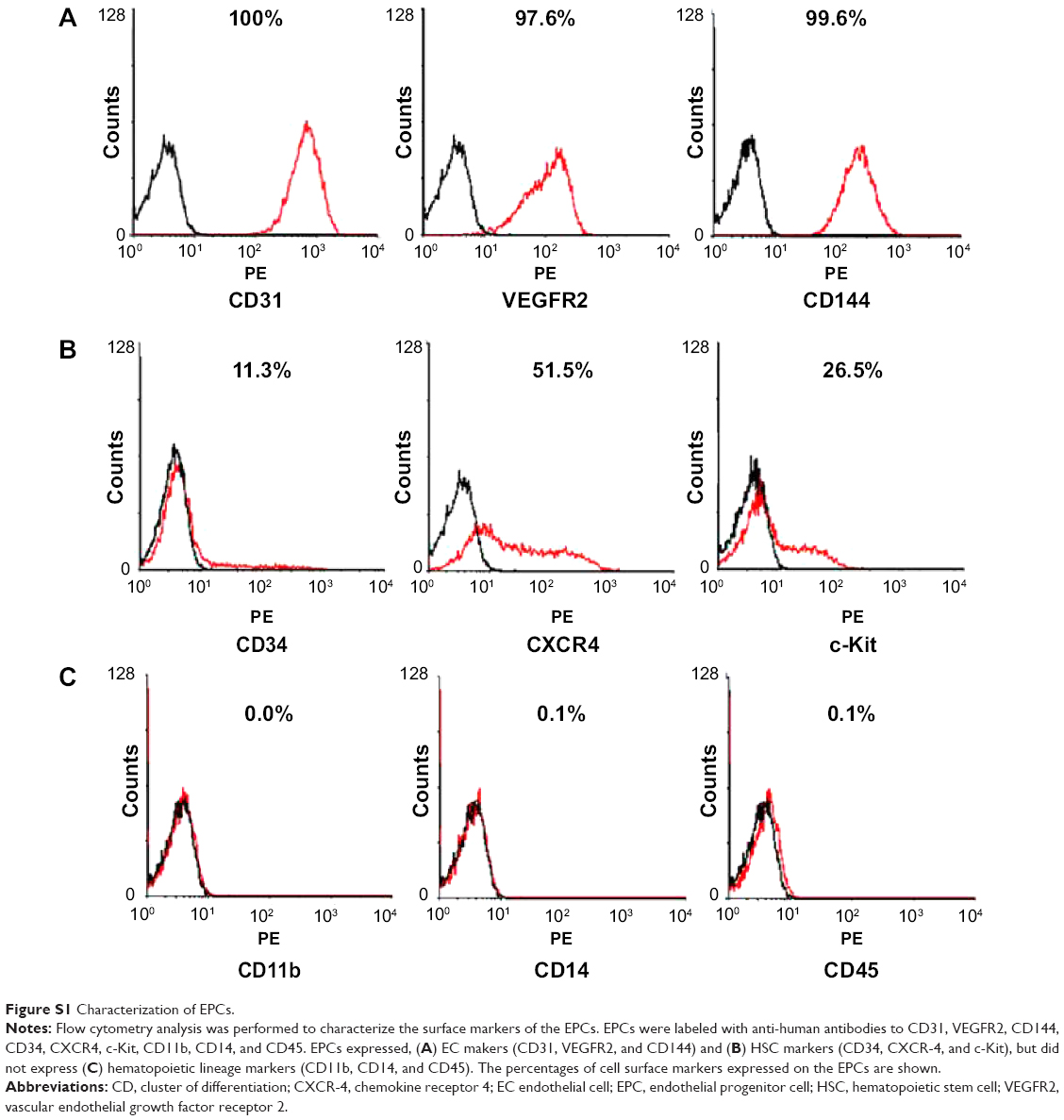 | Figure S1 Characterization of EPCs. |
References
Lee JH, Lee SH, Yoo SY, Asahara T, Kwon SM. CD34 hybrid cells promote endothelial colony-forming cell bioactivity and therapeutic potential for ischemic diseases. Arterioscler Thromb Vasc Biol. 2013;33(7):1622–1634. | ||
Lee SH, Lee JH, Yoo SY, Hur J, Kim HS, Kwon SM. Hypoxia inhibits cellular senescence to restore the therapeutic potential of old human endothelial progenitor cells via the hypoxia-inducible factor-1alpha-TWIST-p21 axis. Arterioscler Thromb Vasc Biol. 2013;33(10):2407–2414. |
 © 2015 The Author(s). This work is published and licensed by Dove Medical Press Limited. The full terms of this license are available at https://www.dovepress.com/terms.php and incorporate the Creative Commons Attribution - Non Commercial (unported, v3.0) License.
By accessing the work you hereby accept the Terms. Non-commercial uses of the work are permitted without any further permission from Dove Medical Press Limited, provided the work is properly attributed. For permission for commercial use of this work, please see paragraphs 4.2 and 5 of our Terms.
© 2015 The Author(s). This work is published and licensed by Dove Medical Press Limited. The full terms of this license are available at https://www.dovepress.com/terms.php and incorporate the Creative Commons Attribution - Non Commercial (unported, v3.0) License.
By accessing the work you hereby accept the Terms. Non-commercial uses of the work are permitted without any further permission from Dove Medical Press Limited, provided the work is properly attributed. For permission for commercial use of this work, please see paragraphs 4.2 and 5 of our Terms.