")
Back to Journals » International Journal of Nanomedicine » Volume 9 » Issue 1
The development, fabrication, and material characterization of polypropylene composites reinforced with carbon nanofiber and hydroxyapatite nanorod hybrid fillers
Authors Liao CZ, Wong H, Yeung KWK, Tjong SC
Received 26 November 2013
Accepted for publication 22 December 2013
Published 11 March 2014 Volume 2014:9(1) Pages 1299—1310
DOI https://doi.org/10.2147/IJN.S58332
Checked for plagiarism Yes
Review by Single anonymous peer review
Peer reviewer comments 4
Cheng Zhu Liao,1,2 Hoi Man Wong,3 Kelvin Wai Kwok Yeung,3 Sie Chin Tjong2
1Department of Materials Science and Engineering, South University of Science and Technology of China, Shenzhen, People's Republic of China; 2Department of Physics and Materials Science, City University of Hong Kong, 3Department of Orthopedics and Traumatology, Li Ka Shing Faculty of Medicine, University of Hong Kong, Hong Kong
Abstract: This study focuses on the design, fabrication, microstructural and property characterization, and biocompatibility evaluation of polypropylene (PP) reinforced with carbon nanofiber (CNF) and hydroxyapatite nanorod (HANR) fillers. The purpose is to develop advanced PP/CNF–HANR hybrids with good mechanical behavior, thermal stability, and excellent biocompatibility for use as craniofacial implants in orthopedics. Several material-examination techniques, including X-ray diffraction, Fourier-transform infrared spectroscopy, scanning electron microscopy, thermogravimetric analysis, differential scanning calorimetry, tensile tests, and impact measurement are used to characterize the microstructural, mechanical, and thermal properties of the hybrids. Furthermore, osteoblastic cell cultivation and colorimetric assay are also employed for assessing their viability on the composites. The CNF and HANR filler hybridization yields an improvement in Young's modulus, impact strength, thermal stability, and biocompatibility of PP. The PP/2% CNF–20% HANR hybrid composite is found to exhibit the highest elastic modulus, tensile strength, thermal stability, and biocompatibility.
Keywords: nanocomposite, implant, cellular viability, mechanical behavior
Introduction
There has been growing interest amongst materials scientists, biomedical engineers, and surgeons in the use of novel biomaterials for the treatment of severe skeletal defects and injuries in recent years. Human bone defects can be caused by trauma, cancer, infection, and congenital abnormality. Autografts taken from the patient’s bones and allografts from cadavers are typically used for replacing bone-tissue defects. However, limited supply of autografts and the immunological rejection reaction of allografts are their main drawbacks. In this respect, artificial implants are considered as alternative materials for treating bone disease and trauma.
Metallic materials, such as Fe-based alloy (American Iron and Steel Institute 316 stainless steel), Co-based alloy (60.6 wt% Co, 31.5 wt% Cr, 6.0 wt% Mo, 1.9 wt% residuals [Si, Mn and C]; Vitallium®), and Ti-based alloy (Ti–6 wt% Al–4 wt% V) are typically used as implants in orthopedics. However, metallic materials have many disadvantages for use as bone-replacement implants. Corrosion and wear are major concerns of the long-term performance of metallic prosthesis. Fe-based stainless alloy may suffer pitting corrosion upon exposure to human body fluid containing about 0.9% NaCl.1 This is because chloride ion destroys passive film formed on stainless steel. Moreover, some metallic ions and wear debris released from metallic implants can cause allergy and infection.2–4 Aluminum ions released from the Ti–6 wt% Al–4 wt% V alloy can induce Alzheimer’s disease, while vanadium ions can modify enzyme activity of the cells. The toxicity of vanadium has driven the development of novel biomaterials for replacing Ti–6Al–4V. Furthermore, Young’s modulus of metallic implants is much higher than that of human cortical bone, leading to the so-called stress-shielding effect. Stress shielding is the inhomogeneous transfer of stress between the implant and bone. Young’s moduli of 316 stainless steel, CoCrMo alloy, and Ti–6Al–4V alloy are in the ranges of 205–210 GPa, 220–230 GPa, and 115 GPa respectively. They are much higher than Young’s modulus of human cortical bone, which ranges from 7 to 30 GPa.5
Bone tissue is a biocomposite with hydroxyapatite (HA) nanoplatelets dispersed in the collagen matrix. The HA mineral exhibits high hardness and excellent biocompatibility, osteoconductivity, and bioactivity. The designed biocomposites for load-bearing biomedical applications should combine the advantages of both components.6 However, synthetic HA collagen composites possess low mechanical strength, and thus are typically used for biodegradable scaffolds in orthopedics.7,8 To enhance the mechanical performance of biocomposites, nondegradable polymers, such as high-density polyethylene (HDPE), have been selected as the matrix of HA-reinforced PE composite (HAPEX™).9–11 The incorporation of 40 vol% HA microparticles into HDPE results in a considerable increase in its elastic modulus. However, HAPEX with low tensile strength is mainly used for orbital floor prosthesis, middle ear implant, and maxillofacial surgery. Furthermore, large HA particles with sizes of several micrometers often debond readily from the polymer matrix and fracture into small fragments during mechanical testing.12
Recent progress in nanotechnology has allowed the synthesis of nanomaterials with excellent physical and mechanical properties,13 as well as biocompatibility.14,15 For example, synthetic nanoscale HA strongly promotes the adhesion and proliferation of osteoblasts.16–18 Carbon nanotubes (CNTs) with exceptionally high Young’s modulus (about 1 TPa) and excellent electrical conductivity show good biocompatibility towards human cells like osteoblasts, myoblasts, and neurons.19–22 In this context, nano-HA and CNTs have been employed as reinforcing fillers for polymers in forming functional composites for biomedical applications.23–32 However, CNTs with coiled morphology disperse poorly in the polymeric matrix, especially at higher filler contents. This leads to inferior mechanical performance of the resulting composites. In contrast, carbon nanofibers (CNFs) with a straight feature can better disperse in the polymeric matrix of biocomposites. Other advantages of CNFs include lower production cost and good biocompatibility. In this regard, CNFs have been incorporated into polymers to form functional composites for biomedical applications.33,34 CNFs are generally synthesized by the catalytic decomposition of hydrocarbons on transition metal catalysts, such as Fe, Co, and Cu nanoparticles, at high temperatures.35–37 Straight and helical CNFs can be selectively prepared by properly monitoring the reaction temperature, feed-gas composition, and the shape of metal nanoparticles. In the latter case, Jian et al reported that spherical Cu nanoparticles favor formation of straight CNFs, while polyhedral or facetted Cu catalysts yield helical CNFs.37
In a previous study, we prepared polypropylene (PP) composites with 5–20 wt% HA nanorods (HANRs).25 The results showed that the addition of 20 wt% HANRs (6.67 vol%) to PP improves its mechanical performance and biocompatibility. PP exhibits excellent chemical resistance, durability, dimensional stability, and flexibility. PP exhibits higher fatigue resistance than HDPE, and thus can replace ductile HDPE for biomedical implants experiencing frequent cyclic stress. In this study, we investigated the influence of CNF additions on the structural, thermal, and mechanical behaviors of PP and PP/20 wt% HANR composites. In the latter case, low CNF loadings (0.5–2 wt%) were added to the PP/20 wt% HANR composite to yield hybrids with higher mechanical performance and biocompatibility. The aim was to develop polymer-composite implants with good biocompatibility for bone-defect repair and replacement, especially for craniofacial applications.
Materials and methods
Materials
PP (Moplen HP500N) was purchased from LyondellBasell Polymers (Saudi Arabia). CNFs of 50–200 nm (diameter) and 0.5–20 μm (length) were obtained from Nanostructured and Amorphous Materials (Houston, TX, USA). HANRs were purchased from Nanjing Emperor Nano Materials (Nanjing, People’s Republic of China), with an average width of 20 nm and length of 120 nm.
Preparation of nanocomposites
Table 1 list the compositions of PP/CNF and PP/CNF–HANR composites. The precursor materials of these composites were first melt-extruded in a Brabender (Duisburg, Germany) with blending temperature profiles of 215°C, 230°C, 230°C, 220°C, 195°C, and 180°C at a rotation speed of 40 rpm. The extrudates were pelletized and blended again in the Brabender. The obtained materials were granulized again, dried, and subsequently injection-molded into rectangular plaques. Pure PP and PP/20% HANR nanocomposite were also fabricated under the same processing conditions.
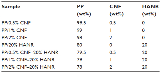 | Table 1 Composition of the composites investigated |
Characterization
X-ray diffraction (XRD) experiments were carried out with a Siemens (Munich, Germany) D500 diffractometer (Cu-Kα radiation) operating at 40 kV and 30 mA. Fourier-transform infrared (FTIR) spectra in the range of 400–4,000 cm−1 were recorded with a PerkinElmer (Waltham, MA, USA) spectrometer (16PC). Morphological analysis of the composites was performed in a JEOL (Tokyo, Japan) field-emission scanning electron microscope (FE-SEM; JSM-7100F). The crystallization behavior of PP/CNF and PP/CNF–HANR nanocomposites was studied using a differential scanning calorimeter (DSC; model 2910; TA Instruments, New Castle, DE, USA) purged with nitrogen. The specimen was first scanned from room temperature to 200°C at 100°C/minute, then held for 3 minutes to delete its previous thermal history, followed by cooling at 10°C/minute. Thermogravimetric experiments were performed with a TGA Q50 (TA Instruments) in a nitrogen atmosphere from 30°C to 550°C at 20°C/minute. The temperature at 5% weight loss (T5%) was determined from the weight loss-versus-temperature curves.
Tensile and notched impact specimens were prepared from injection-molded plaques. Tensile tests were performed with an Instron Corporation (Norwood, MA, USA) tester (model 5567) at room temperature at 10 mm/minute based on the ASTM D638-08. The Izod impact tests were performed with an impact tester (CEAST model 6545; Instron) according to the ASTM D256-05. Both tensile and impact tests employed six specimens of each composite material, and the average values were determined accordingly.
Cell culture and proliferation
For the cell-culture experiment, the human osteoblast cell line Saos-2 was grown in Dulbecco’s Modified Eagle’s Medium (DMEM) with 10% fetal bovine serum and penicillin/streptomycin. The samples were sterilized with 70% ethanol and rinsed with sterile phosphate-buffered saline (PBS). Then, 100 μL medium containing 104 cells was seeded on sterile samples placed into the wells of a 96-well culture plate. The plate was put into an incubator at 37°C under a humidified atmosphere with 5% CO2 and 95% air. After cultivation for 48 and 96 hours, respectively, the specimens were rinsed with PBS and treated with 10% formaldehyde. They were then dehydrated with a series of graded ethanol solutions, followed by critical point drying. The cellular constructs were sputter-coated with gold, and imaged in a scanning electron microscope (SEM).
The cell viability of samples was determined with a 3-(4,5-dimethylthiazol-2-yl)-2,5-diphenyltetrazolium bromide (MTT) assay. Samples placed in a 96-well plate were seeded with 100 μL suspension with 104 cells. This plate was put into an incubator at 37°C in a humidified atmosphere of 95% air and 5% CO2 for periods of 2, 4, 7, and 10 days. The DMEM was refreshed every 3 days. After the desired incubation period, sterile MTT solution of 10 μL was added to each well and kept for a further 4 hours to obtain insoluble formazan crystals. Finally, 100 μL of 10% sodium dodecyl sulfate 0.01 M HCl was added to each well to dissolve formazan crystals. The light absorbance in each well was determined at 570 nm using a multimode detector (DTX 880; Beckman Coulter, Pasadena, CA, USA), with a background correction at 640 nm. The well with 100 μL cell suspension and the well without cells (DMEM only) were employed as the positive and negative controls, respectively. The number of samples for each material in the tests was five, and the MTT assay tests were repeated at least twice. Data were reported as means and standard deviation.
Results and discussion
Structural and morphological analyses
Figure 1 shows the XRD patterns of PP and PP-based composites. Pristine PP is characterized by diffraction peaks at 2θ =14.1°, 16.9°, 18.5°, 21.2°, and 21.8° associated with the (110), (040), (130), (111), and (041) reflections. The HANR peaks occur at 26.0°, 28.3°, 29.0° 31.9°, 33.0°, and 34.2°, corresponding to the (002), (102), (210), (211), (112), and (300) planes. It can be seen that the incorporation of CNF and/or HANR nanofillers into the polymer matrix does not induce structural change of the PP lattice.
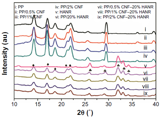 | Figure 1 X-ray diffraction patterns of PP, HANR and their composites. |
Figure 2 shows the FTIR spectra of PP and HANR and their composites. The absorption bands of the PO43− group of HANR (trace V) appear at 963 and 470 cm−1 (γ1 and γ2 vibration mode), 1,034 and 1,092 cm−1 (γ3 mode of P–O symmetric stretching vibration), and 565 and 601 cm−1 (γ4 P–O bending vibration).38 The peaks at 3,569 and 631 cm−1 are attributed to the hydroxide (OH−) stretching mode. The spectra of the PP/20% HANR and PP/1% CNF–20% HANR nanocomposites reveal the presence of HANR with its phosphate-group peaks at ~1,050, 565, and 601 cm−1, and the hydroxide-group band at 3,659 cm−1.
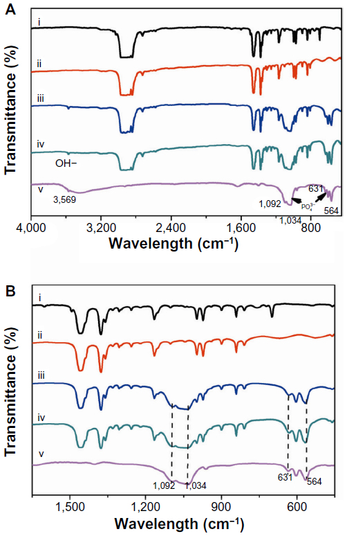 | Figure 2 (A) Fourier-transform infrared spectra of PP (i), PP/1% CNF (ii), PP/20% nHA (iii), PP/1% CNF-20% nHA (iv), and nHA (v) specimens. (B) FTIR spectra of these specimens from 450 to 1,650 cm–1. |
Figure 3 is a typical SEM image of CNFs showing a straight-rod morphology. Such CNFs supplied by Nanostructured and Amorphous Materials are used as the reinforcement material for PP to form composites. Figure 4A is the SEM image of PP/20% HANR composite. Some HANR agglomerates can be observed due to its higher filler loading. The HANR content of 20 wt% is needed for anchoring and supporting the growth of osteoblasts. For the PP/0.5% CNF–20% HANR and PP/2% CNF–20% HANR hybrid composites, CNFs with straight features disperse uniformly in the PP matrix (Figure 4B and C).
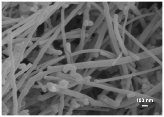 | Figure 3 Scanning electron microscopy image of carbon nanofibers. |
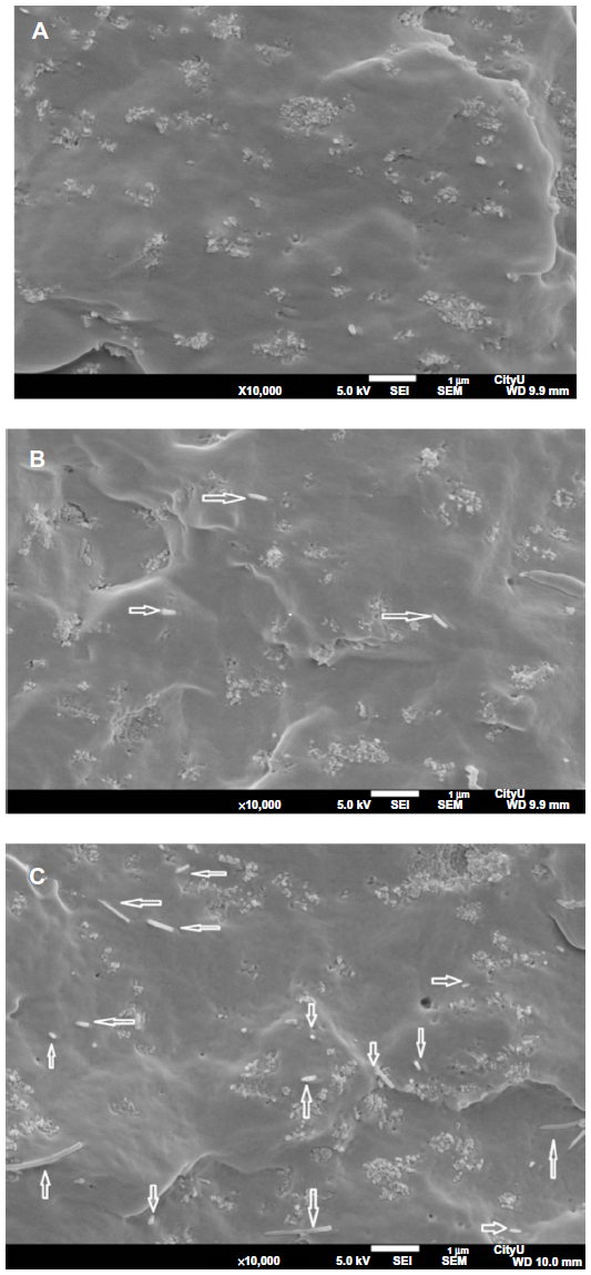 | Figure 4 Scanning electron micrographs of PP/20% HANR (A), PP/0.5% CNF–20% HANR (B), and PP/2% CNF–20% HANR (C) composites. White arrows indicate CNFs. |
Thermal behavior
Figure 5 shows the thermogravimetric analysis (TGA) curves of pure PP, binary PP/CNF, PP/20% HANR, and ternary PP/CNF–HANR nanocomposites. The T5% values of all the specimens are tabulated in Table 2. This table reveals that the T5% of PP improves greatly either by adding 20% HANR or low CNF-loading levels. This demonstrates that both CNF and HANR nanofillers are very effective for reducing the degradation of PP at high temperatures. Furthermore, hybridization of CNFs with HANR fillers further enhances the T5% value of the resulting composites. The PP/2% CNF–20% HANR hybrid nanocomposite exhibits the highest T5% value of 444.6°C. High T5% values are generally needed for biocomposites, since artificial implants are subjected to sterilization in the surgical operation.
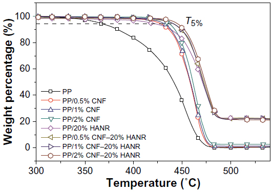 | Figure 5 Thermogravimetric analysis curves of PP, PP/0.5% CNF, PP/1% CNF, PP/2% CNF, PP/20% HANR, PP/0.5% CNF–20% HANR, PP/1% CNF–20% HANR, and PP/2% CNF–20% HANR specimens. |
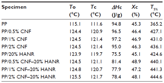 | Table 2 Thermal parameters of the samples investigated |
Figure 6 shows the DSC cooling traces of PP, PP/20% HANR, PP/CNF, and PP/CNF–HANR samples. The onset crystallization temperature (To), peak crystallization (Tc) temperature, and the crystallization enthalpy (ΔHc) are also listed in Table 2. The degree of crystallinity (Χc) of PP and its nanocomposites can be determined from:

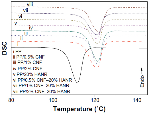 | Figure 6 Differential scanning calorimetry (DSC) cooling curves of PP, PP/0.5% CNF, PP/1% CNF, PP/2% CNF, PP/20% HANR, PP/0.5% CNF–20% HANR, PP/1% CNF–20% HANR, and PP/2% CNF–20% HANR specimens. |
where ΔHm is the melting enthalpy of the 100% crystalline PP, ie, 209 J/g,39,40 and f is the weight fraction of the filler of the nanocomposites. For pure PP, f=0. The DSC parameters of the aforementioned specimens are tabulated in Table 2. Apparently, DSC results clearly demonstrate that the HANR and CNF additions influence crystallization of PP greatly. Both the To and Tc values of PP increase considerably with the inclusion of CNF and/or HANR nanofillers. The To value of pure PP is 115.1°C, and rises to 123.9°C by adding 20 wt% HANR. The Tc value of PP/20% HANR nanocomposite can be further increased to 125.5°C by adding 2 wt% CNFs. The Xc value of PP is almost unchanged by adding 20 wt% HANR. However, the additions of 0.5–2 wt% CNFs to the PP/20% HANR nanocomposites increase its crystallinity. Therefore, CNF nanofillers are effective nucleating sites for PP crystallites in the PP/HANR composites upon cooling from the melt.
Mechanical properties
Figure 7A and B show the elastic modulus and tensile strength versus CNF content for the PP/CNF and PP/CNF–HANR composite systems, respectively. The tensile properties of these specimens are summarized in Table 3. It is obvious that the stiffness of PP increases with increasing CNF content. Furthermore, the stiffness of PP increases markedly from 1.36 GPa to 2.28 GPa by adding 20 wt% HANR (6.67 vol%), being 67.6% improvement. Higher HANR content is added to PP with bioinertness for anchoring and proliferation of osteoblasts on its surface. Hybridization of CNF with HANR further enhances the stiffness of PP. The PP/2% CNF–20% HANR hybrid exhibits a maximum stiffness value of 2.52 GPa, an 85.2% enhancement over pure PP.
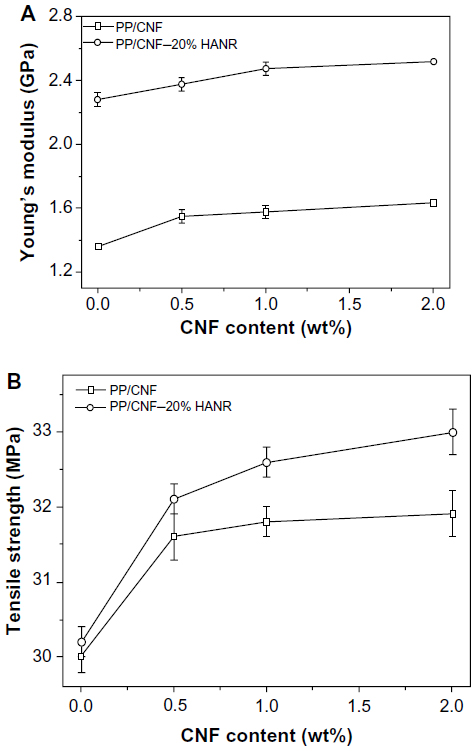 | Figure 7 Young’s modulus (A) and tensile strength (B) versus CNF content of PP/CNF and PP/CNF–20% HANR systems. |
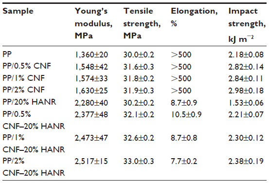 | Table 3 Mechanical properties of PP-based composites |
Liu and Wang investigated the tensile behavior of PP/10–25 vol% HA (24.5 μm) composites.41 They found that the Young’s modulus of PP (1.30 GPa) increases with HA content up to 25 vol%. The stiffness of the PP/25 vol% HA composite reaches 2.73 GPa. However, the tensile strength of PP (ie, 29.55 MPa) and elongation at fracture decrease markedly with increasing filler content. At 25 vol% HA, the tensile strength reduces to 20.16 MPa. These results clearly show that large HA particles of micrometer size are ineffective to improve the PP tensile strength.
From Table 3, the modulus and tensile strength of PP/20 wt% (6.67 vol%) HANR nanocomposite are 2.28 GPa and 30.2 MPa, respectively. The stiffness of this nanocomposite is slightly smaller than that of the PP/25 vol% HA microcomposite, but the tensile strength is much higher than that of the PP/25 vol% HA microcomposite. It should be noted that the filler content of the PP/6.67 vol% HANR nanocomposite is nearly a quarter less than that of the PP/25 vol% HA microcomposite. When 2 wt% CNF is added to the PP/20 wt% (6.67 vol%) HANR nanocomposite, its modulus and tensile strength reaches 2.52 GPa and 33.0 MPa, respectively. This table also reveals that the elongation at break of PP (>500%) decreases sharply with the addition of rigid HANR. For the PP/20 wt% HANR, the elongation reduces to only 8.7%. In contrast, the addition of 0.5–2wt% CNFs to PP does not lead to a deterioration of its fracture elongation. The PP/CNF nanocomposites still retain high tensile ductility (>500%).
Figure 8 shows the Izod impact strength versus CNF content for the PP/CNF and PP/CNF–20% HANR nanocomposite systems. The Izod test results of the specimens investigated are listed in Table 3. Obviously, the impact strength of PP improves considerably as the CNF loading increases. However, the impact toughness of PP reduces markedly to 1.53 kJ m2 by adding 20 wt% HANR. The toughness of the PP/20% HANR composite can be restored by CNF additions. The impact strength of PP/CNF–20% HANR containing 0.5–2 wt% CNFs ranges from 2.21 to 2.38 kJ m−2, higher than that of PP, having a value of 2.18 kJ m−2.
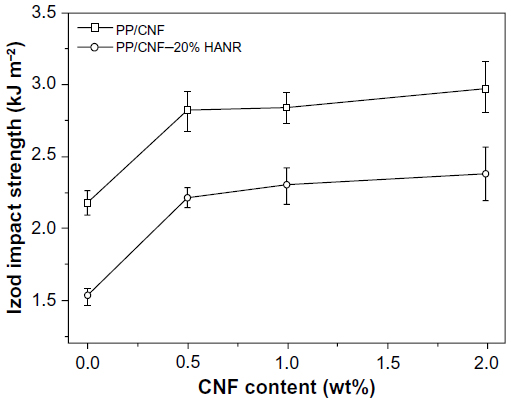 | Figure 8 Impact strength versus CNF content of PP/CNF and PP/CNF–20% HANR systems. |
It is generally known that several mechanical failure modes, such as fiber breakage, crack bridging, crack deflection, and fiber pullout will take place in polymer composites filled with short fibers. In general, crack bridging contributes to an enhancement in the toughness of such microcomposites greatly. During mechanical deformation, the propagating crack is bridged by the fibers that are not fractured completely and capable of load-bearing activity. Apparently, CNFs with large aspect ratios can behave as carbon short fibers that bridge the grown cracks, leading to enhanced tensile elongation and impact strength of the PP/CNF and PP/CNF–20% HANR nanocomposite systems, as shown in Figure 8 and Table 3.
From these results, it appears that the CNF additions are beneficial for enhancing tensile modulus and tensile strength of the PP/20% HANR composite (Figure 7A and B). Moreover, CNF additions do not degrade tensile elongation or impact toughness of the PP/CNF–20% HANR nanocomposite system, but rather improve them. The mechanical properties of the hybrid composites are closely related to their microstructural features, especially the dispersion of nanofillers. Microstructural examination of the hybrid composites reveals that straight CNFs are dispersed homogeneously in the polymer matrix (Figure 4B and C). In other words, CNFs do not cluster into agglomerates that degrade mechanical performance of the composites. On the contrary, CNTs are well known to disperse nonuniformly in the polymer composites. Accordingly, uniformly dispersed CNFs can carry applied loads effectively during tensile tests, leading to enhanced tensile properties of the PP/CNF–20% HANR nanocomposite system.
Cell cultivation and viability
Figure 9A and B are respective SEM images of pure PP cultivated with osteoblasts for 2 and 4 days. Very few cells are anchored on PP, as expected due to its bioinertness. By adding CNFs to PP, the number of anchored cells increases (Figures 10 and 11), particularly for the PP/2% CNF nanocomposite cultured for 4 days (Figure 11B). This implies that CNFs serve as preferential regions for anchoring osteoblasts. This is due to the good bioactivity and biocompatibility of the CNFs.14,15 Similarly, a large number of osteoblasts are seen to anchor on the PP/20% HANR composite (Figure 12), demonstrating the promotion effect of osteoblast adhesion by inorganic HANR fillers. By combining the bioactivity advantages of both CNFs and HANR, the cells colonize the hybrid-composite surfaces (Figures 13A and 14A) and spread over the whole surfaces after seeding for 4 days (Figures 13B and 14B). A high-magnification view of osteoblast cells showing the anchoring of long filopodia to the composite surface is shown in Figure 14C. This implies that the hybrid fillers provide sites for cell adhesion and proliferation.
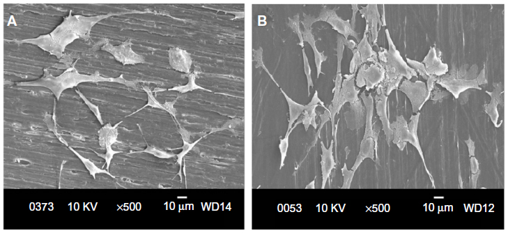 | Figure 9 Scanning electron micrographs of cultured osteoblasts on pure PP for 2 days (A) and 4 days (B). |
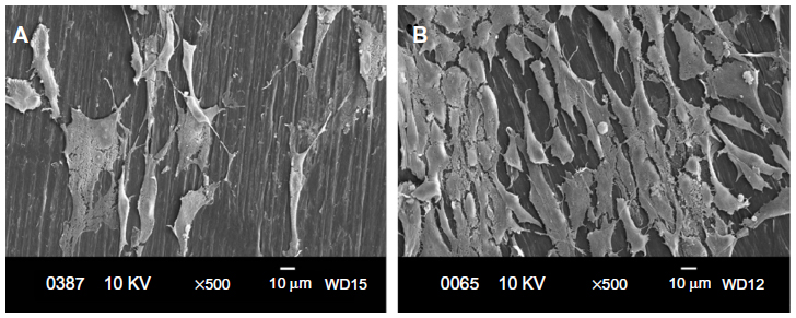 | Figure 11 Scanning electron micrographs of cultured osteoblasts on PP/2% CNF composite for 2 days (A) and 4 days (B). |
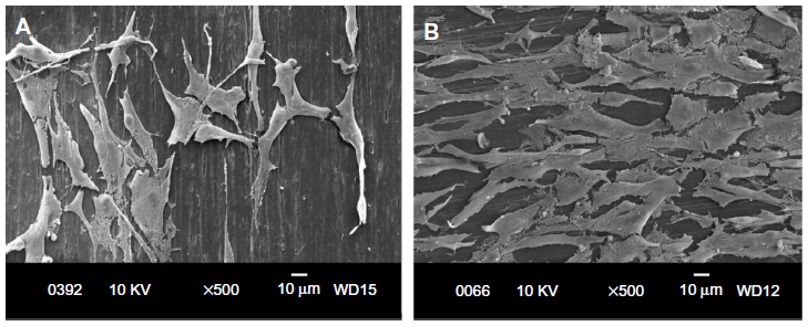 | Figure 12 Scanning electron micrographs of cultured osteoblasts on PP/20% HANR composite for 2 days (A) and 4 days (B). |
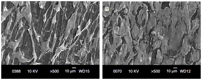 | Figure 13 Scanning electron micrographs of cultured osteoblasts on PP/0.5% CNF–20% HANR hybrid composite for 2 days (A) and 4 days (B). |
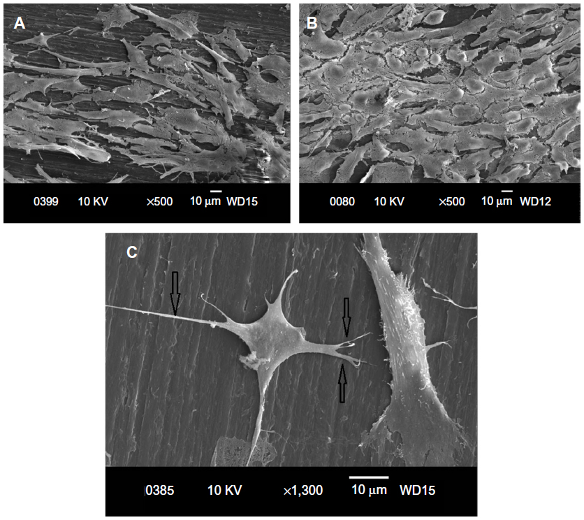 | Figure 14 Scanning electron micrographs of cultured osteoblasts on PP/2% CNF–20% HANR hybrid composite for 2 days (A) and 4 days (B). (C) High magnified SE image showing long filopodias. |
The good bioactivity and biocompatibility of the CNFs are attributed to their nanoscale dimensions. The size of CNFs resembles the dimension of collagen fibrils and protein components of human bones. Price at al investigated the effects of dimension, surface energy, and chemistry of carbon fibers on selective bone cell adhesion.20 They reported that CNFs with diameters <100 nm are more effective than carbon fibers with diameters >100 nm and other metallic alloys (Ti–6Al–4V and CoCrMo) for promoting osteoblast adhesion. Furthermore, CNFs without pyrolytic layers having higher surface energy exhibit enhanced osteoblastic adhesion, but reduce the seeding of fibroblasts, chondrocytes, and smooth-muscle cells. As recognized, the adhesion of osteoblasts onto nanomaterials is mediated through selected protein interaction, such as with integrin.22 Zhang and Webster demonstrated that nanomaterials with favorable cell-surface characteristics promote extensive protein interaction and adhesion, thereby stimulating bone growth.15
From the literature, attachment, adhesion, and spreading in bone implants are required for osteogenic cells to proliferate on their surfaces.42 The MTT assay has been recommended by the International Standards Organization (ISO) for the evaluation of biocompatibility of medical devices, ie, ISO 10993-5.43 The evaluation of cell viability should encompass a negative control testing the absence of cytotoxic effects; ISO109935-1 recommends high-density polyethylene.44 In this study, the well with cell suspension and the well without cells were employed as the positive and negative controls, respectively.
Cellular viability is determined from the following equation:

Figure 15A shows the MTT results for pure PP, PP/20% HANR, PP/0.5% CNF, and PP/0.5% CNF–20% HANR specimens cultivated for 2, 4, 7, and 10 days. The osteoblast viability for the PP/2% CNF and PP/2% CNF–20% HANR composites with higher CNF content is shown in Figure 15B. From Figure 15A, the osteoblast viability on these samples rises with increasing cultivation period up to 10 days. For pure PP, the cell viability is slightly below 30% after 4 days of culture, corresponding to cytotoxicity effects. The viability of PP/0.5% CNF–20% HANR is 45% after 4 days and reaches 68% upon cultivation for 10 days. By increasing CNF content in the hybrid to 2 wt%, the PP/2% CNF–20% HANR composite is found to exhibit the highest osteoblast viability on day 10 – 78%. Therefore, the cell viability of PP can be improved markedly by adding 2% CNF and 20% HANR fillers. The MTT results for all samples cultured for 4 and 10 days are summarized in Figure 16.
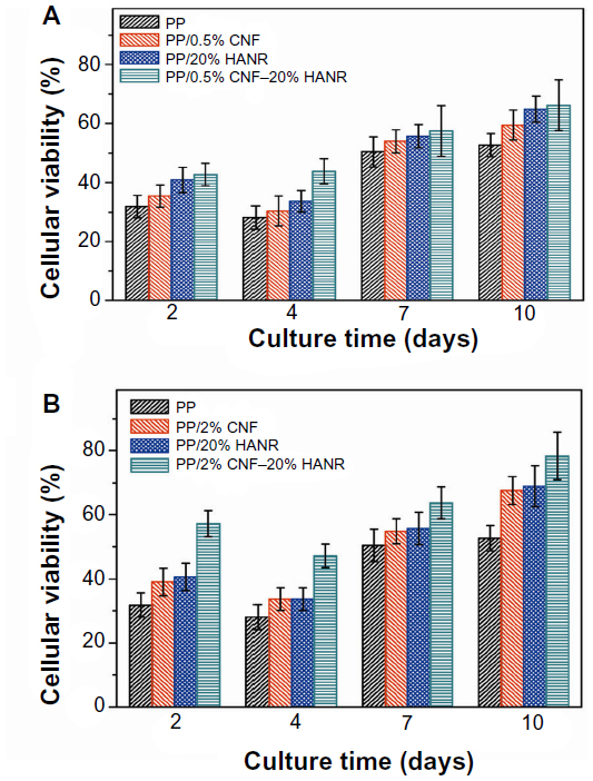 | Figure 15 Cell viability of cultured osteoblasts on PP, PP/20% HANR, PP/20% HANR, PP/CNF, and PP/CNF–HANR nanocomposites. Error bars represent mean standard deviation of five identical specimens. |
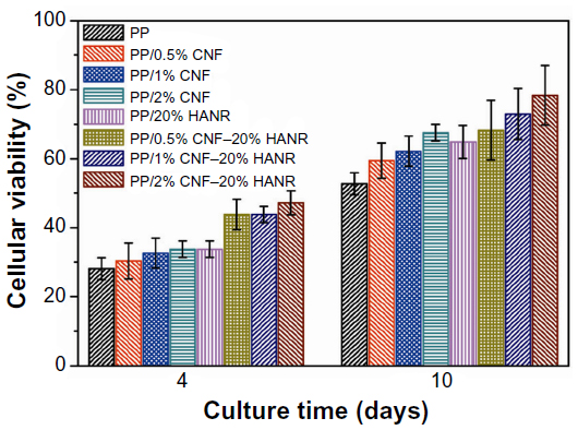 | Figure 16 Cell viability of cultured osteoblasts on PP and its nanocomposites. |
For the MTT assay, the amount of formazan crystals produced is directly proportional to the number of metabolically active cells in the culture. However, this assay can yield lower cell-viability values upon cultivation with CNTs. Wörle-Knirsch et al exposed the human alveolar epithelial cell line A549 to single-walled CNTs and reported that the MTT assay produces considerable loss in cell viability, due to the MTT formazan crystals clumping together with CNTs. Such a lumped formazan–CNT mixture dissolves poorly in organic solvents, eg, propanol/HCl or acetone.45 This interference does not affect the enzymatic reaction, but results from the insoluble nature of MTT formazan crystals. However, the salt (2-[4-iodophenyl]-3-[4-nitrophenyl]-5 -[2,4-disulfophenyl]-2H-tetrazolium) used in the WST-1 assay can yield a water-soluble formazan product, and thus no solvent extraction is needed. From the MTT results, the PP/2% CNF–20% HANR hybrid exhibits the highest cellular viability. It is considered that the interference of CNF on MTT test results causes a reduction in cell viability. More extensive investigations should be done in future to elucidate this issue by employing other cell-viability assays.
Conclusion
We fabricated PP/CNF nanocomposites and PP/CNF–20% HANR hybrids using melt-compounding and injection-molding processes. The influences of low CNF loadings on the microstructural, mechanical, and thermal properties as well as the cellular viability of PP were investigated. The results show that CNF additions improve the elastic modulus and tensile strength of PP without sacrificing its tensile ductility and impact toughness. Further enhancement in tensile properties of PP can be achieved by hybridizing CNF with HANR fillers. The PP/2% CNF–20% HANR hybrid shows highest stiffness and tensile strength. TGA tests reveal that the thermal stability of PP improves markedly either by adding 20% HANR or low CNF-loading levels. The PP/2% CNF–20% HANR hybrid also exhibits the highest T5% value of 444.6°C. DSC measurements indicate that CNFs act as effective nucleating sites for PP crystallites upon cooling from the melt. Finally, CNF nanofillers promote osteoblastic adhesion and viability on PP. The MTT results reveal that the PP/2% CNF–20% HANR hybrid exhibits good biocompatibility for osteoblasts.
Acknowledgment
This work was supported by an Applied Research Grant (9667071), City University of Hong Kong.
Disclosure
The authors report no conflicts of interest in this work.
References
Yu J, Zhao ZJ, Li LX. Corrosion fatigue resistances of surgical implant stainless steels and titanium alloy. Corros Sci. 1993;35(1–4):587–591. | |
Metikas-Hukovic´ M, Kwokal A, Piljac J. The influence of niobium and vanadium on passivity of titanium-based implants in physiological solution. Biomaterials. 2003;24(21):3765–3775. | |
Kim TI, Han JH, Lee IS, Lee KH, Shin MC, Choi BB. New titanium alloys for biomaterials: a study of mechanical and corrosion properties and cytotoxicity. Biomed Mater Eng. 1997;7(4):253–263. | |
Tjong SC, Lau KC. Properties and abrasive wear of TiB2/Al-4%Cu composites produced by hot isostatic pressing. Compos Sci Technol. 1999;59(13):2005–2013. | |
Hench LL, Wilson J. An Introduction to Bioceramics. Singapore: World Scientific; 1993. | |
Roeder RK, Converse GL, Kane RJ, Yue W. Hydroxyapatite-reinforced polymer biocomposites for synthetic bone substitutes. JOM. 2008;60(3):38–45. | |
Sachlos E, Wahl DA, Triffitt JT, Czernuszka JT. The impact of critical point drying with liquid carbon dioxide on collagen-hydroxyapatite composite scaffolds. Acta Biomater. 2008;4(5):1322–1331. | |
Ngiam M, Liao SS, Patil AJ, Cheng ZY, Chan CK, Ramakrishna S. The fabrication of nano-hydroxyapatite on PLGA and PLGA/collagen nanofibrous composite scaffolds and their effects in osteoblastic behavior for bone tissue engineering. Bone. 2009;45(1):4–16. | |
Huang J, Disilvio L, Wang M, Tanner KE, Bonfield W. In vitro mechanical and biological assessment of hydroxyapatite-reinforced polyethylene composite. J Mater Sci Mater Med. 1997;8(12):775–779. | |
Guild FJ, Bonfield W. Predictive modelling of the mechanical properties and failure processes in hydroxyapatite-polyethylene (HapexTM) composite. J Mater Sci Mater Med. 1998;9(9):497–502. | |
Wang M, Joseph R, Bonfield W. Hydroxyapatite-high density polyethylene composites: effect of ceramic particle size and morphology. Biomaterials. 1998;19(24):2357–2366. | |
Abu Bakar MS, Cheang P, Khor KA. Mechanical properties of injection molded hydroxyapatite-polyetheretherketone biocomposites. Compos Sci Technol. 2003;63(3–4):421–425. | |
Tjong SC, Chen H. Nanocrystalline materials and coatings. Mater Sci Eng R Rep. 2004;45(1–2):1–88. | |
Yang L, Zhang LJ, Webster TJ. Nanobiomaterials: state of the art and future trends. Adv Eng Mater. 2011;13(6):B197–B217. | |
Zhang LJ, Webster TJ. Nanotechnology and nanomaterials: promises for improved tissue regeneration. Nano Today. 2009;4(1):66–80. | |
Ergun C, Liu HN, Halloran JW, Webster TJ. Increased osteoblast adhesion on nanograined hydroxyapatite and tricalcium phosphate containing calcium titanate. J Biomed Mater Res A. 2007;80(4):990–997. | |
Li K, Tjong SC. Hydrothermal synthesis and bio-mineralization of hydroxyapatite nanorods. J Nanosci Nanotechnol. 2011;11:10444–10448. | |
Zhou H, Lee J. Nanoscale hydroxyapatite particles for bone tissue engineering. Acta Biomater. 2011;7(7):2769–2781. | |
Smart SK, Cassady AI, Lu G, Martin DJ. The biocompatibility of carbon nanotubes. Carbon. 2006;44(6):1034–1047. | |
Price RL, Waid M, Haberstroh K, Webster TJ. Selective bone cell adhesion on formulations containing carbon nanofibers. Biomaterials. 2003;24(11):1877–1887. | |
Li XM, Gao H, Uo M, et al. Effect of carbon nanotubes on cellular functions in vitro. J Biomed Mater Res A. 2009;91A(1):132–139. | |
Newman P, Minett A, Ellis-Behnke R, Zreiqat H. Carbon nanotubes: their potential and pitfalls for bone tissue regeneration and engineering. Nanomedicine. 2013;9(8):1139–1158. | |
Li K, Yeung Yeung CY, Yeung KW, Tjong SC. Sintered hydroxyapatite/polyetheretherketone nanocomposites: mechanical behavior and biocompatibility. Adv Eng Mater. 2012;14(4):B155–B165. | |
Li K, Tjong SC. Mechanical, thermal and bioactive behaviors of polyamide 6/hydroxyapatite nanocomposites. J Nanosci Nanotechnol. 2011;11(12):10644–10648. | |
Liao CZ, Li K, Wong HM, Tong WY, Yeung KW, Tjong SC. Novel polypropylene biocomposites reinforced with carbon nanotubes and hydroxyapatite nanorods for bone replacements. Mater Sci Eng C Mater Biol Appl. 2013;33(3):1380–1388. | |
Tjong SC. Structural and mechanical properties of polymer nanocomposites. Mater Sci Eng R Rep. 2006;53(3–4):73–197. | |
Gilmore KJ, Moulton SE, Wallace GG. Incorporation of carbon nanotubes into the biomedical polymer poly(styrene-β-isobutylene-β-styrene). Carbon. 2007;45(2):402–410. | |
Kumar NA, Ganapathy HS, Kim JS, Jeong YS, Jeong YT. Preparation of poly 2-hydroxyethyl methacrylate functionalized carbon nanotubes as novel biomaterial nanocomposites. Eur Polym J. 2008;44(3):579–586. | |
Wang L, Weng L, Song S, Zhang Z, Tian S, Ma R. Characterization of polyetheretherketone-hydroxyapatite nanocomposite materials. Mater Sci Eng A. 2011;528(10–11):3689–3696. | |
Ormsby R, McNally T, O’Hare P, Burke G, Mitchell C, Dunne N. Fatigue and biocompatibility properties of a poly(methyl methacrylate) bone cement with multi-walled carbon nanotubes. Acta Biomater. 2012;8(3):1201–1212. | |
Khang D, Kim SY, Liu-Snyder P, Palmore GT, Durbin SM, Webster TJ. Enhanced fibronectin adsorption on carbon nanotube/poly(carbonate) urethane: independent role of surface nano-roughness and associated surface energy. Biomaterials. 2007;28(32):4756–4768. | |
Yang L, Zhang LJ, Webster TJ. Carbon nanostructures for orthopedic medical applications. Nanomedicine. 2011;6(7):1231–1244. | |
Stout DA, Basu B, Webster TJ. Poly(lactic-co-glycolic acid): carbon nanofiber composites for myocardial tissue engineering applications. Acta Biomater. 2011;7(8):3101–3112. | |
Tsang M, Chun YW, Im YM, Khang D, Webster TJ. Effects of increasing carbon nanofiber density in polyurethane composites for inhibiting bladder cancer cell functions. Tissue Eng Part A. 2011;17(13–14):1879–1889. | |
Mukhopadhyay K, Porwal D, Lal D, Ram K, Mathur GN. Synthesis of coiled/straight carbon nanofibers by catalytic chemical vapor deposition. Carbon. 2004;42(15):3254–3256. | |
Li X, Xu Z. Controllable synthesis of helical, straight, hollow and nitrogen-doped carbon nanofibers and their magnetic properties. Mater Res Bull. 2012;47(12):4383–4391. | |
Jian X, Jiang M, Zhou Z, et al. Gas-induced formation of Cu nanoparticle as catalyst for high-purity straight and helical carbon nanofibers. ACS Nano. 2012;6(10):8611–8619. | |
Bertinetti L, Tampieri A, Landi E, et al. Surface structure, hydration, and cationic sites of nanohydroxyapatite: UHR-TEM, IR, and microgravimetric studies. J Phys Chem C. 2007;111(10):4027–4035. | |
Mark JE. Physical Properties of Polymer Handbook. New York: AIP; 1996. | |
Stojanovic´ Z, Kac̆arevic´-Popovic´ Z, Galovic´ S, Milic̆evic´ D, Suljovrujic´ E. Crystallinity changes and melting behavior of the uniaxially oriented iPP exposed to high doses of gamma radiation. Polym Degrad Stab. 2005;87(2):279–286. | |
Liu Y, Wang M. Fabrication and characteristics of hydroxyapatite reinforced polypropylene as a bone analogue material. J Appl Polym Sci. 2007;106(4):2780–2790. | |
Anselme K. Osteoblast adhesion on biomaterials. Biomaterials. 2000;21(7):667–681. | |
International Organization for Standardization. ISO 10993-5:2009: Biological evaluation of medical devices – part 5: tests for in vitro cytotoxicity. 2009. | |
International Organization for Standardization. ISO 10993-1:2009: Biological evaluation of medical devices – part 1: evaluation and testing within a risk management process. 2009. | |
Wörle-Knirsch JM, Pulskamp K, Krug HF. Oops they did it again! Carbon nanotubes hoax scientists in viability assays. Nano Lett. 2006;6(6):1261–1268. |
 © 2014 The Author(s). This work is published and licensed by Dove Medical Press Limited. The full terms of this license are available at https://www.dovepress.com/terms.php and incorporate the Creative Commons Attribution - Non Commercial (unported, v3.0) License.
By accessing the work you hereby accept the Terms. Non-commercial uses of the work are permitted without any further permission from Dove Medical Press Limited, provided the work is properly attributed. For permission for commercial use of this work, please see paragraphs 4.2 and 5 of our Terms.
© 2014 The Author(s). This work is published and licensed by Dove Medical Press Limited. The full terms of this license are available at https://www.dovepress.com/terms.php and incorporate the Creative Commons Attribution - Non Commercial (unported, v3.0) License.
By accessing the work you hereby accept the Terms. Non-commercial uses of the work are permitted without any further permission from Dove Medical Press Limited, provided the work is properly attributed. For permission for commercial use of this work, please see paragraphs 4.2 and 5 of our Terms.