")
Back to Archived Journals » Energy and Emission Control Technologies » Volume 3
Maisotsenko cycle: technology overview and energy-saving potential in cooling systems
Authors Rogdakis E, Tertipis D
Received 25 October 2014
Accepted for publication 23 January 2015
Published 6 March 2015 Volume 2015:3 Pages 15—22
DOI https://doi.org/10.2147/EECT.S62995
Checked for plagiarism Yes
Review by Single anonymous peer review
Peer reviewer comments 4
Editor who approved publication: Dr Adolfo Perujo
Emmanuel D Rogdakis, Dimitrios Nik Tertipis
Faculty of Mechanical Engineering, National Technical University of Athens, Athens, Greece
Abstract: The present paper deals with an overview of Maisotsenko cycle (M-cycle). This cycle is an indirect evaporative cooling–based cycle, which utilizes a smart geometrical configuration for the air distribution. The achievement of this geometry is the high efficiency of the cycle, as it produces cold air of temperature lower than the wet-bulb ambient air temperature. As the energy source of this cooler is water rather than electricity, the usage of M-cycle–based coolers leads to significant energy saving, more than 80% in terms of electricity. The heat and mass exchanger is analyzed and described in detail, so the specifications of M-cycle will be clear and understandable. The operation of the standard configuration of M-cycle is studied thereafter and useful conclusions are carried out, about the efficiency and the energy consumption (electricity and water). Finally, the energy-saving potential is estimated in conventional cooling systems, in terms of electricity and capital cost, in order to evaluate the financial benefit of M-cycle application: the pay-back period is calculated equal to about 2.5 years (as the result of the replacement of conventional systems with M-cycle–based ones). The study is to be a useful tool to anyone interested in energy saving in buildings and in industrial plants, as the operating cost, which is strongly affected by the cooling demand, is significantly reduced by the application of M-cycle.
Keywords: M-cycle, evaporative cooling, high efficiency, renewable energy, energy saving, low CO2 emission
Introduction
Although conventional air-conditioning systems are widely accepted to be of high energy consumption, they cover a significant part of needs for air-conditioning. Scientific research focus on improved refrigerants (the global warming potential of which is lower than that of restricted R-12 or R-22) or more effective compressors; however, the high operational cost of these units as well as its role in atmospheric pollution cannot significantly be limited. As the dangerous environmental effects of chlorofluorocarbons and greenhouse gases (not only as direct emissions, but also as indirect emissions) have been reduced, the interest is focused on environment-friendly cooling technologies. The energy consumed for heating and cooling of domestic premises accounts for 7% of the national total energy demand; nevertheless, it is responsible for 29% of the CO2 emissions. Especially in Greece, ambient temperatures have a direct impact on the pattern of the nation’s power demand, while buildings are generally cooled by conventional vapor compression systems.1
Evaporative air-conditioning is a really promising technology. Whereas conventional systems use chlorofluorocarbon based refrigerants (CFCs), evaporative coolers (ECs) use water. Evaporation technology is simple and functional and has both residential and industrial applications, achieving significant efficiencies in suitable climates (hot and dry).
ECs are based on water evaporation and latent heat utilization. When water evaporates and becomes vapor, the heat is removed from the air, resulting in a cooler air temperature. As they do not use any compressor or pump, apart from some fans, their electricity demand is very low, while they can provide the cooling areas with air of satisfactory temperature (about 19°C–21°C). Substantial energy, no chlorofluorocarbon usage, reduced peak demand, reduced CO2 and power plant emissions, improved indoor air quality, lifecycle, cost effectiveness, easily integrated into built-up systems, and easy to use with direct digital control are the main advantages of ECs. On the contrary, some types of ECs produce an air stream of extremely high humidity (sometimes, the stream is almost saturated) and consume a significant amount of water.
There are two basic categories of EC: direct and indirect.
- According to the first configuration, the water evaporates into the air to be cooled; as a result, the product air is cold and wet. A typical direct EC (DEC) consists of a box with voluminous humidification blocks, a water pump, and a water distribution system. The fan draws in warm and dry ambient air through the wet blocks, cooling it. The latent heat of the air is used to evaporate the water. Evaporation cools the air while increasing its moisture content or relative humidity. No heat is added or taken out of the air; thus, it is an adiabatic process of constant enthalpy.
- On the other hand, indirect ECs (IECs) are based on two different streams (working [wor] and product [pro]), in order to get a relatively drier product stream, but its temperature is not as low as it would be by a DEC. A heat exchange layer is used between the working airstream and the supply airstream, because the ambient wet-bulb (wb) temperature is theoretically the minimum achievable temperature of a conventional evaporative system. A typical IEC system can achieve an efficiency of about 55%.
An ideal EC would produce air as cool as the wet-bulb temperature, while a real cooler cannot reach such a low temperature. Thus, the efficiency of the ECs is defined as the ratio of current to maximum possible temperature drop:
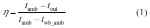
DECs achieve high values of efficiency (80%–95%); however, IECs cannot achieve a value higher than 55%.
Maisotsenko cycle (M-cycle) applies an improved design of indirect evaporative cooling. Keeping the humidity ratio of product air constant, it succeeds in decreasing the air temperature down to ambient wet-bulb temperature and close to ambient dew-point (dp) temperature, by a smart heat and mass transfer procedure. Paper sheets of a special type, for optimum wetting and mass transfer between them and the air, are used as exchange layers, while the product air (which is to cool the air-conditioning spaces) is totally protected by moisture of supplying water.2
M-cycle has been designed to optimize the effectiveness of both stages of evaporation (direct evaporation of working stream and heat exchange between streams). Instead of one-stage evaporating (which is applied in conventional evaporative systems), M-cycle is based on a multi-evaporating approach, which allows to it to achieve high values of effectiveness, higher than 105%.3
ECs based on M-cycle have been already installed to supply cool air to various applications (domestic cooling, commercial and industrial buildings, etc). The advantages of this technology in comparison to conventional refrigeration systems or to typical IECs are the lower energy demand (reaches 85% in terms of electricity) and the lower product air temperature. Theoretically, if all conventional air-conditioning systems, installed in buildings, would be substituted by evaporative ones, based on M-cycle, the estimated reduction of CO2 emission would be equal to about 24%!
This paper aims at describing in a simple way the M-cycle operation and utilization and at presenting some useful experimental data, to prove the high efficiency of M-cycle, under Mediterranean climate conditions. Although ECs cannot achieve as low temperature as their users want (due to the dew-point temperature restriction), M-cycle is the most effective IEC, the product air of which tends to the outlet air temperature of conventional building air-conditioning systems. And, as it is a quite new technology (about 8 years), its improvement potential in terms of electricity consumption is not negligible.
M-cycle principles and technical overview
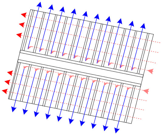
The first step of M-cycle construction is to create the “paths” of dry channels. Both working (pink lines) and product (red lines) streams use dry channels (Figure 1). The working stream passes through the perforations and is driven to the wet channels (blue lines, Figure 2).
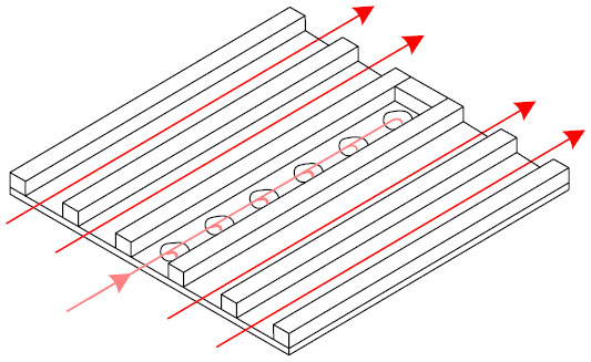 | Figure 1 Dry channels configuration. |
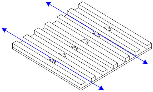 | Figure 2 Wet channels configuration. |
Figure 2 helps in understanding the M-cycle: the working stream, which will evaporate the water, is precooled under constant relative humidity (as no mass exchanging takes place along the dry channels). It enters the wet channels under lower temperature than ambient temperature, and the wet-bulb temperature, which is eliminated at each working channel, is related to the inlet temperature. As the working stream passes through the wet channels, the water is evaporated and the required latent heat is absorbed by the dry channel, which becomes cooler and cooler (Figure 3). In reality, one layer of heat and mass exchanger (HMX) is show on Figure 4.
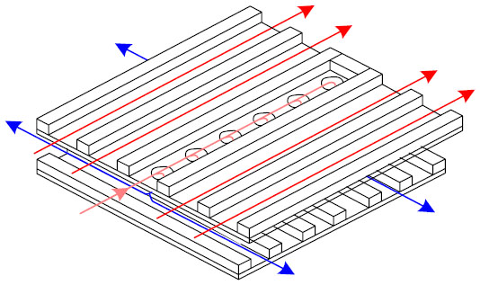 | Figure 3 Heat and mass exchanging. |
 | Figure 4 Heat and mass exchanger layer configuration. |
An M-cycle–based cooled is structured by 40 heat and mass exchanging layers, creating the following apparatus (Figure 5). Some auxiliary devices (fans and pump) are needed to drive the air and the water into the cooler.
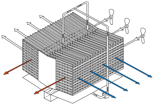 | Figure 5 Maisotsenko-cycle cooler configuration. |
- The basic principle of the M-cycle is that the temperature difference between the stream is higher than in a typical IEC.4
- The product stream, of mass flow m, enters the cooler at level “up” and is led through parallel channels, which are maintained dry and smooth, so no humidity is added or removed from the stream. As it always happens in IECs, the humidity ratio of the product stream is kept constant along the cooler.
- The working stream, of mass flow M, also enters the cooler at the upper level and is driven through dry channels at this level. As it meets the perforations, an amount of this is led to the lower level, which is always wet. Due to the contact of the working air with the wet surface of the channels at the lower level, the evaporation of the water takes place and the working stream is cooled. This cooling absorbs heat from the working stream while it is at the upper level (which is consequently precooled, so being cooler than the ambient air, it is driven to the heat exchanging zone) and from the product stream, while they are both in the zone of heat exchanging. At this zone the product air is cooled and the working stream is exhausted, almost saturated, and cooler than the ambient air. Theoretically, the minimum possible temperature of state is the ambient air dew point; however, generally this state is between the ambient air wet bulb and the dew point.
Precooling of the working stream improves the cooler efficiency comparatively to simple indirect evaporative systems; in terms of efficiency, the M-cycle achieves an efficiency of 90%–125%. Its efficiency is significantly affected by flow rates and ambient conditions and is expressed in wet-bulb terms, in order to indicate the better performance of a Maisotsenko cooler instead of a typical EC.
M-cycle cooler performance
Evaporation in an IEC is caused 1) by the sensible heat of the working stream and 2) by the sensible heat of the product stream. It is clear that, because the two currents do not interact, any water addition will not affect the product stream and its contribution to the increase of the latent heat, which causes evaporation, is linked to the temperature difference of the two streams.5
The scope of this section is the estimation of the cooling capacity, specific water consumption (swc) and efficiency of the M-cycle–based cooler, under common Mediterranean ambient conditions during the summer period (between 33°C and 36.5°C). To evaluate the performance of an M-cycle–based device, a HMX of a nominal cooling capacity of 0.35 RT was used (it is equal to about 4,200 BTU/h or 1.23 kWc) (Figure 6).
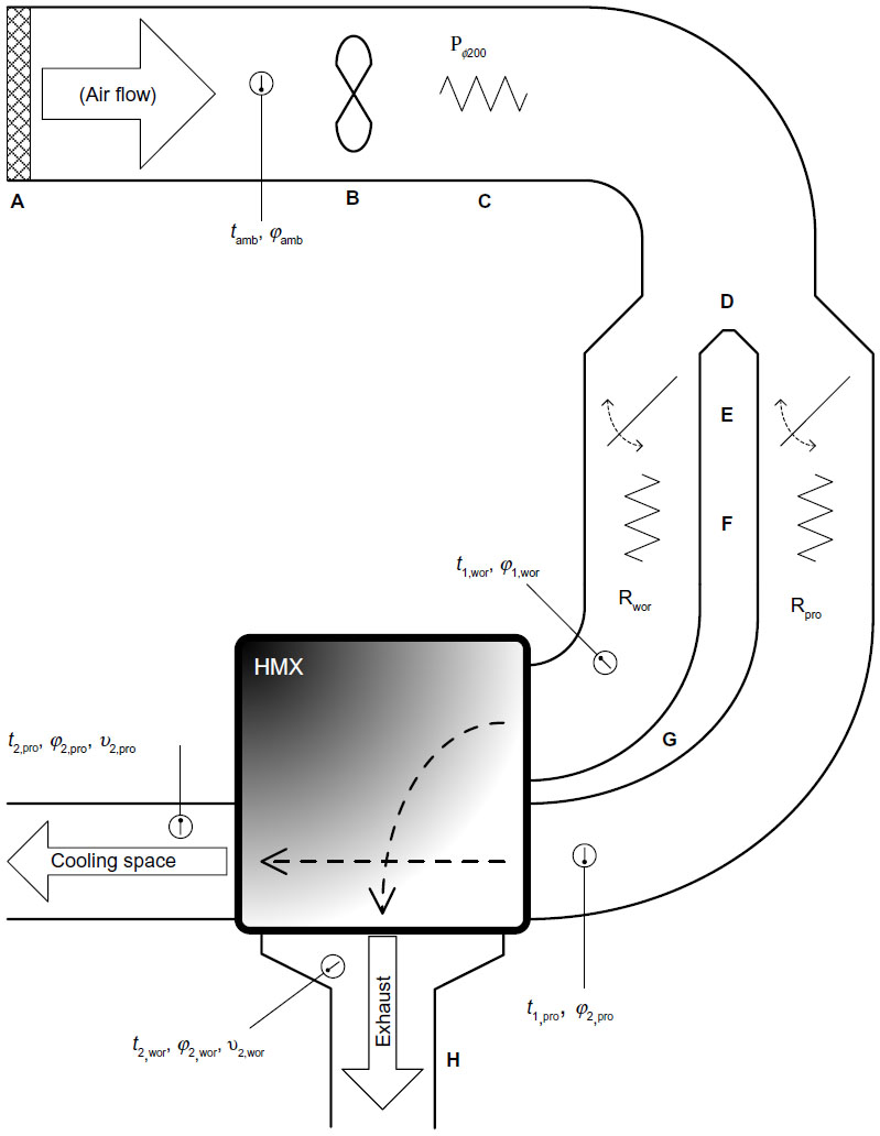 | Figure 6 Experimental rig. |
The experimental rig consists of the following devices and parts:
- Main suction duct: a flexible, isolated φ200 duct is used. The entire air passes through this duct.
- Fan: an axial two-speed fan is used, 80 W/120 W of power and 800 m3/h at 2,000 rpm or 1,100 m3/h at 2,500 rpm of nominal air flow.
- Secondary resistor: a resistor of 1,000 W power is used for assistance in air preheating. Due to its position, this resistor heats the whole air, before splitting the streams.
- Splitter: for splitting the two streams (working and product), a heat isolated “inverted Y” splitter is used. Each stream is channeled to φ150 ducts.
- Air flow regulators: the air flow of each stream is independently controlled. Contrary to the fan, whose speed control refers to the entire quantity of air, here there are two regulators (one for each stream).
- Main resistors: each of the two main resistors (of 1,000 W) was placed in the interior of the duct of each stream. The halt of electricity has been secured in case the fan is disabled, so as to avoid any superheating of the resistors.
- Stream ducts: these two isolated φ150 air ducts lead each current to the HMX after it has been preheated.
- Exhaust stream duct: in order to stop the wet air suction by the main suction duct (and exchanger malfunction), the highly humidified working stream is rejected in the atmosphere fairly away from the main air duct entrance.
For measurements, the following instruments were used:
➢ Air flow: velocity probes, of accuracy ±0.2 m/s. The hotwire was placed in the center of each air duct, so as to measure the maximum velocity.
➢ Temperature: thermometers, of accuracy ±0.2°C.
➢ Relative humidity: probes of accuracy ±1%.
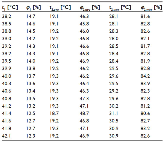
The measurement procedure results are shown in Table 1.
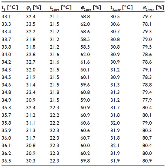 | Table 1 Ambient (1), cooled air (2), and exhaust air (2) conditions |
During the measurement procedure, the mass flow of both streams was mpro = mwor = 0.024 kgda/s (it is reminded that the cooled air is heavier than the exhaust air, due to its low temperature).
As for the cooling capacity, it tends to increase as the ambient temperature increases because the temperature drop tends to increase under higher ambient temperature (at “boundary” conditions the temperature drops were Δt = 12.0°C at 33.1°C and Δt = 14.2°C at 36.5°C). The correlation of the ambient temperature with the heat available for evaporation is also clear: below 33.1°C, the exhaust stream had a humidity ratio W2,wor = 0.221 kgw/kgda, while below the maximum temperature it had W2,wor = 0.244 kgw/kgda (ie, the evaporation effectiveness increased).6
Usually, the evaporating cooler manufacturers give a typical value of hourly water consumption; however, this value does not take into account the cooler efficiency. For this reason, the specific water consumption was defined, which is equal to the amount of water the evaporation of which can produce 1 kWhc. This parameter can be easily calculated and applied generally in each EC, without any additional information about the cooler size, mass flow, and capacity, so the EC becomes “dimensionless”. Using the experimental data, it is concluded that the specific water consumption tends to reduce as the ambient temperature increases due to a higher increase of the cooling capacity, varying between 2.5 kgw/kWhc and 3.0 kgw/kWhc.
The increased amount of heat inserted in the cooler, when the ambient air is hotter, reinforces the evaporation phenomenon, as already mentioned, resulting in higher temperature drops through the cooler. The efficiency of the cooler is directly affected, as the higher the temperature, the more effective the cooler. The results show that an efficiency of about 90% is easily achieved, as the cooler efficiency (additionally, under lower capacity than the nominal) is always greater than 97%, while at a high ambient temperature, the efficiency reaches 102%.7
M-Cycle cooler operation optimization
The most effective way to optimize the operation of an EC based on M-cycle is to adjust the ratio λ = mpro/mwor. In comparison to the nominal setting of λ = 1:
- if λ<1, the water evaporation is stronger (in terms of specific water consumption) and the produced air temperature is lower
- if λ>1, the water evaporation is weaker and the produced air temperature is higher.
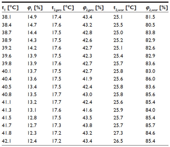
Two cases of limited mass flow were examined. Specifically, the ratio λ was adjusted to 1:1, 1:2, and 2:1; the measurements taken are presented in Tables 2–4, respectively.
 | Table 2 Nominal air supply conditions (λ = 1:1) |
 | Table 3 Efficiency improving by λ adjustment (λ = 1:2) |
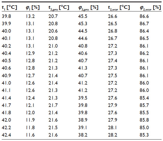 | Table 4 Consumption improving by λ adjustment (λ = 2:1) |
Taking as a fact that any configuration in the cooler operation is a “deviation” to its standard specifications, a decline of the capacity is initially expected. It is clear that a lower product stream flow affects the cooling capacity because the larger enthalpy drop between cooled and ambient air does not cover the lowered flow of 50%. If the working stream flow is limited, the weakening of the evaporation (so the temperature drop in the product stream is lower) works as an obstacle to the cooling capacity, but not as much as a limited product stream flow does. Consequently, if the aim is to achieve the highest cooling capacity possible, the cooler should work on λ = 1:1 (ie, under its standard specification).
As for the specific water consumption, the results are clear regarding the working stream flow reduction, where the production of 1 kWhc needs about 55% less water, but there is no clear tendency when the working stream flow is reduced. So, if we aim to minimize water consumption, the lowering of the working stream mass flow is the best solution (the cooler consumes less than 1.5 kgw/kWhc).8
There is no doubt about the effect of the reduction of the product stream flow on the improvement of the cooler efficiency. For λ = 1:2, the cooler reaches a 115% efficiency (while for λ = 1:1 would lead to 107%), “gaining” 2°C of additional cooling. On the contrary, it is shown how disastrous a reduction of the working stream flow can be because the poor evaporation makes the cooler inefficient for significant temperature drops. Even then, in this case, the efficiency is comparable to that of DECs, even without producing humid air like these and almost double the efficiency of typical indirect evaporative systems.
Energy-saving potential in cooling systems
The replacement of conventional cooling systems by ones based on M-cycle leads to a significant environmental benefit, as:
- the electricity consumption is much lower (about 80%) and
- dangerous refrigerants are not used, as water is an 100% renewable energy source.
In this chapter, a commercial cooler based on M-cycle is compared to a conventional one of the same cooling capacity:
- evaporative cooler
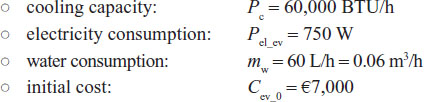
- conventional cooler
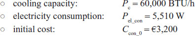
As the electricity cost is about 0.14 €/kWh and the water cost is about 0.60 €/m3, the cost of two alternatives can be calculated as a function of operation hours:
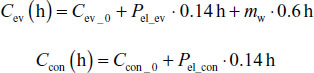
Ignoring the rates of return, it is clear that at about 6,000 hours of operation (Figure 7), the increased cost of installation of an EC balances the increased cost of operation of an conventional cooler. Thus, the payback period of an EC, compared to a conventional one, is about 2.5 years.
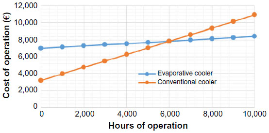 | Figure 7 Operational cost of evaporative cooler and of a conventional cooler. |
Conclusion
In this paper, a cooler utilizing the M-cycle is analyzed; the aim was the production of dry and cool air with low electricity consumption (only a simple axial fan of 750 W consumes electricity) and improvements of the cooler characteristics (efficiency and water consumption). The measurements took place at a fairly dry climate and, without any modification, the cooler can achieve more than 100% efficiency. The efficiency does not depend on the ambient conditions, but the product stream temperature, which is to be driven to the cooled space, is strongly affected by the humidity of the region where the cooler is installed. The specific water consumption of the cooler under normal mode varies (under common ambient conditions) between 2.5 kgw/kWhc and 3.0 kgw/kWhc.
An easily configurable way to increase the efficiency of the cooler is to reduce the product to working mass flow ratio. However, this method leads to a significant increase of specific water consumption. Given that the increase in efficiency and decrease in consumption are both desirable, the product channel mass flow configuration is proposed, as this can increase the efficiency about 10% and reduce the specific water consumption about 15%.
It was also important to understand the energy-saving potential of an EC, based on M-cycle. As it consumes about 80% less electricity than a conventional cooler, its high installation cost is quickly balanced by its lower operation cost.
As a conclusion, M-cycle can satisfy the cooling demand of most Greek cities and it is also expected to do at other Mediterranean regions (of similar ambient conditions), without consuming high amounts of electricity and water. At humid climates, the cycle could not be recommended, as both product air temperature and hourly consumption are rather high.
Disclosure
The authors report no conflicts of interest in this work.
References
Gillan L, Maisotsenko V. Maisotsenko open cycle used for gas turbine power generation. ASME Turbo Expo 2003, Technical Paper No GT2003-38080; 2003. | |
Caliskan H, Hepbasli A, Dincer I, Maisotsenko V. Thermodynamic performance assessment of a novel air cooling cycle. Int J Refrig. 2011;34:980–990. | |
Hasan A. Indirect evaporative cooling of air to a sub wet-bulb temperature. Appl Therm Eng. 2010;30:2460–2468. | |
Bruno F. On-site experimental testing of a novel dew point evaporative cooler. Energy Build. 2011;43:3475–3483. | |
Riangvilaikul B, Kumar S. An experimental study of novel dew-point evaporative cooling system. Energy Build. 2010;42:637–644. | |
Anisimov S, Pandelidis D. Numerical study of perforated indirect evaporative air cooler. Int J Energy Clean Environ. 2011;12(2–4): 239–250. | |
Erens PJ, Dreyer AA. Modelling of indirect evaporative air coolers. Int J Heat Mass Transf. 1993;36(1):17–26. | |
Zhan C, Duan Z, Zhao X, Smith St, Jin H, Riffat S. Comparative study of the performance of the M-cycle counter-flow and cross-flow heat exchangers for indirect evaporative cooling. Energy. 2011;36:6790–6805. |
 © 2015 The Author(s). This work is published and licensed by Dove Medical Press Limited. The full terms of this license are available at https://www.dovepress.com/terms.php and incorporate the Creative Commons Attribution - Non Commercial (unported, v3.0) License.
By accessing the work you hereby accept the Terms. Non-commercial uses of the work are permitted without any further permission from Dove Medical Press Limited, provided the work is properly attributed. For permission for commercial use of this work, please see paragraphs 4.2 and 5 of our Terms.
© 2015 The Author(s). This work is published and licensed by Dove Medical Press Limited. The full terms of this license are available at https://www.dovepress.com/terms.php and incorporate the Creative Commons Attribution - Non Commercial (unported, v3.0) License.
By accessing the work you hereby accept the Terms. Non-commercial uses of the work are permitted without any further permission from Dove Medical Press Limited, provided the work is properly attributed. For permission for commercial use of this work, please see paragraphs 4.2 and 5 of our Terms.