")
Back to Journals » OncoTargets and Therapy » Volume 7
Integration of multidisciplinary technologies for real time target visualization and verification for radiotherapy
Authors Chang W, Chen C, Tai H, Liu C, Chen Y
Received 16 March 2014
Accepted for publication 23 April 2014
Published 23 June 2014 Volume 2014:7 Pages 1143—1150
DOI https://doi.org/10.2147/OTT.S64161
Checked for plagiarism Yes
Review by Single anonymous peer review
Peer reviewer comments 3
Wen-Chung Chang,1,* Chin-Sheng Chen,2,* Hung-Chi Tai,3 Chia-Yuan Liu,4,5 Yu-Jen Chen3
1Department of Electrical Engineering, National Taipei University of Technology, Taipei, Taiwan; 2Graduate Institute of Automation Technology, National Taipei University of Technology, Taipei, Taiwan; 3Department of Radiation Oncology, Mackay Memorial Hospital, Taipei, Taiwan; 4Department of Internal Medicine, Mackay Memorial Hospital, Taipei, Taiwan; 5Department of Medicine, Mackay Medical College, New Taipei City, Taiwan
*These authors contributed equally to this work
Abstract: The current practice of radiotherapy examines target coverage solely from digitally reconstructed beam's eye view (BEV) in a way that is indirectly accessible and that is not in real time. We aimed to visualize treatment targets in real time from each BEV. The image data of phantom or patients from ultrasound (US) and computed tomography (CT) scans were captured to perform image registration. We integrated US, CT, US/CT image registration, robotic manipulation of US, a radiation treatment planning system, and a linear accelerator to constitute an innovative target visualization system. The performance of this algorithm segmented the target organ in CT images, transformed and reconstructed US images to match each orientation, and generated image registration in real time mode with acceptable accuracy. This image transformation allowed physicians to visualize the CT image-reconstructed target via a US probe outside the BEV that was non-coplanar to the beam's plane. It allowed the physicians to remotely control the US probe that was equipped on a robotic arm to dynamically trace and real time monitor the coverage of the target within the BEV during a simulated beam-on situation. This target visualization system may provide a direct remotely accessible and real time way to visualize, verify, and ensure tumor targeting during radiotherapy.
Keywords: ultrasound, computerized tomography, robotic arm, real time target visualization
Introduction
The evolution of conformal radiation therapy (RT) techniques has been advancing along with the development of novel imaging modalities and RT machines. Although the use of conformal RT techniques has been extensively accepted for treatment of malignancies, the current way to integrate computed treatment planning, image guided verification, and beam delivery systems leaves target coverage solely from digitally reconstructed beam’s eye view (BEV), which is not directly accessible and that is not in real time. If the soft tissue target is fixed or is located in bony tissues, this method is precise enough to deliver radiation. Another way to overcome the uncertainty in target localization is to trace the target by using implantable seeds and planar X-rays (such as Cyberknife [Accuray, Sunnyvale, CA, USA] and Brain Lab [Brainlab, Feldkirchen, Germany]), cone beam computed tomography (CT), and/or fluoroscopy. However, the visualization of seeds remains imprecise for visualization of whole volumetric targets. Thus, there remains room to improve precision in the coordination between computed treatment planning, digital reconstructed images from BEV, and real target coverage. Clearly, we need to integrate novel and advancing technologies, including systems of real time imaging modalities, robotic controlled image detection, and image registration, to verify, validate, and justify the use of current advancing RT technologies.
In prostate brachytherapy, the concept of visualization of the target by integrating US, fluoroscopy, CT, and a robotically assisted needling brachytherapy system has been developed.1–4 Moreover, the clinical feasibility and safety trials for registration of transrectal US images and the implants reconstructed from fluoroscopy or CT images have been successfully conducted.5,6 It implies that the target visualization system for nonvisible radiation beams is important and urgently needed. However, the target visualization system for conformal external beam radiotherapy, which is the majority of RT practice, is lacking.
In the present study, we aimed to visualize and localize the treatment targets by using a novel integrated remote controlled and real time image system from each BEV for conformal radiotherapy.
Methods
Customized immobilization device
Using currently available hardware, an immobilization mold was customized to reserve space for the performance of robotic arm movement and US probe placement. An alpha cradle (Smithers Medical Product, Inc., North Canton, OH, USA) was used as the immobilization mold.
Adjustment and performance of radiotherapy treatment planning (RTP)
To integrate the US images with a RTP system, the current algorithm of RTP software (Eclipse; Varian Medical Systems, Palo Alto, CA, USA) was adjusted. We used CT-US registered images to generate a putative target volume and to check if it was located within previously generated BEV. Anatomical structures, putative target volumes, and regions of interest were established. Toward this end, an US- and CT-scan compatible abdominal phantom (CIRS Ltd., Dublin, Ireland) with several anatomical structures inside was used to simulate RT targets (Figure 1A and B). One hepatic cyst in the phantom was selected to simulate the RT target for image registration and RT planning. As demonstrated in Figure 1C to E, the beam arrangement, dose distribution, and BEV generated from digitally reconstructed radiographs have constituted the conventional RTP results without a target visualization system.
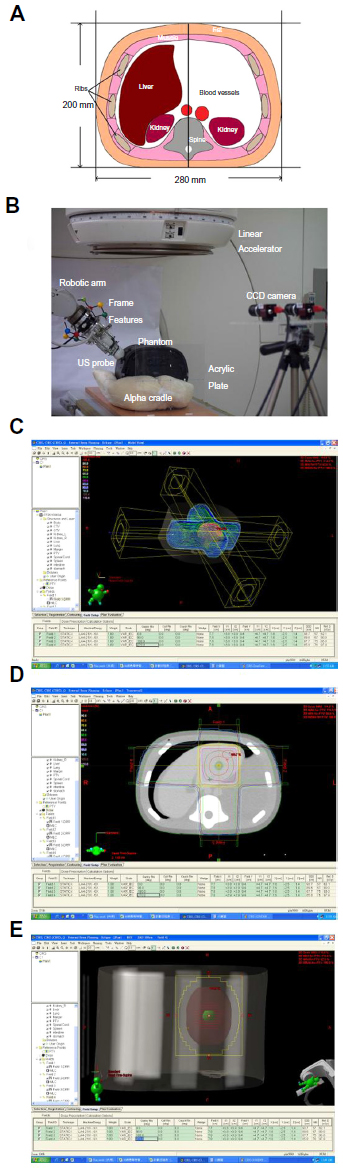 | Figure 1 Phantom and results of radiation treatment planning for the simulated target. |
Remote control of robotic handheld US probe
For the US probe in the RT room to be operated by a physician in real time, a motion following control approach was proposed. Specifically, a 6 degree-of-freedom Mitsubishi RV-1A industrial robotic manipulator equipped with a 6-axis force sensor (ATI Gamma force sensor; ATI Industrial Automation, Apex, NC, USA) and a US probe were employed in the RT room (Figure 1B). The motion command was generated by observing the US probe held by the physician outside the RT room with a pair of color digital charge-coupled device (CCD) cameras (AVT Guppy F-080C; Allied Vision Technologies, Stadtroda, Germany). The proposed system configuration is illustrated in Figure 2A. The position and orientation of the US probe was determined online by extracting preinstalled point and line features as shown in Figure 2B. The probe pose was thus able to be transmitted to the visual servoing system in the RT room as the commanded motion. By using another pair of CCD cameras together with the same preinstalled point and line features, the US probe mounted on the end-effector of the 6-degree of freedom (6-DOF) robotic manipulator was controlled to follow the desired motion. In particular, by properly encoding the hybrid force and pose control task, the US probe mounted on the robotic manipulator in the RT room was accurately moved to the same pose with the desired contact force by stereo visual servoing in real time. Two personal computers, each with an Intel Core 2 Quad Q6600 2.4 GHz CPU, served for computation.
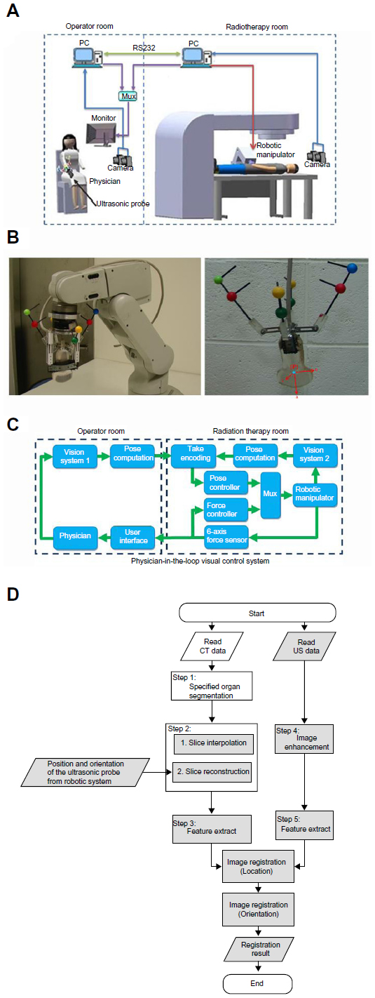 | Figure 2 Composition, configuration, and image registration algorithm for the integrated system. |
The physician-in-the-loop visual servoing control approach
As illustrated in Figure 2A, a physician-in-the-loop visual servoing control approach was proposed. It followed from the known geometry of the preinstalled features. The commanded position r* and orientation θ* were determined based on real time image measurements y* from a two-camera vision system modeled by a perspective projection function G1.

Based on real time image measurements y from the two-camera vision system modeled by G2 in the RT room, the current pose of the US probe held by the robotic manipulator could be similarly computed as follows:

Hence, the pose encoded error involving the difference between the current pose and its commanded value could now be defined as:

The contact force f could be directly measured from the force sensor that was to be maintained at the desired contact force fd. The force encoded error could thus be defined as:

Considering the case of a set point commanded pose, the error dynamics that related the pose encoded error e and the control input u to the robotic manipulator were seen as:

Therefore, the following visual servoing control law was proposed that could drive the hybrid encoded error, involving the pose encoded error and the force encoded error, to zero. It further implied that the hybrid force and pose control task was accomplished with precision.

where uf is the force-control law defined as:

kf is a positive gain constant, and denotes the unit vector normal to the contacting surface.
Coordinate transformations among the US probe, CT images, and the RT machine
To perform real time target localization with the proposed hardware systems, a reference frame, aligned with the isocenter, had to be designed for the purpose. An acrylic plate embedded with metal markers was selected as the reference frame where the origin was aligned with the isocenter of the RT machine. The CT images were extracted offline by scanning the phantom together with the reference frame. Thus, the CT images could be processed with respect to the reference frame. The two-camera vision system was employed to observe the metal markers on the acrylic plate and the point/line features preinstalled on the US probe. Therefore, the coordinate transformations could be determined online from the US probe to the CT images, and then the RT machine via the reference frame where the accuracy could be up to the calibration resolution of the two cameras. By employing available high resolution cameras and offline calibration techniques, this error could be made comparably lower than the positioning error when using existing offline-planned therapy approaches.
Edge-based image registration and computation for clinical target volume (CTV) using US and CT scans
We proposed an edge-based image registration between CT and US images as shown in Figure 2D. The detailed procedures are described as follows: Step 1, the region growing method was first utilized to segment the target organ in the CT image where the seed point given for the region growing method in the target organ was indicated by a clinical doctor in the operator room. This semiautomatic process could improve the reliability and efficiency of segmentation. Step 2, since the physical resolution in each slice (x–y plane in Figure 3A) of the CT images was different to the distance between each slice (z axis in Figure 3A), an interpolation algorithm was proposed to make sure the three dimensional CT-volume data had the same physical resolution in each dimension. In this study, the resolution in CT-volume data was 0.54 mm/pixel. Then the reconstructed slice was extracted by the position and the orientation of the US probe from the robotic system to confirm that the CT and US images were in the same orientation. Step 3, due to the speckle noise and distortion in the US image, we utilized anisotropic diffusion and median filters to enhance the image. They were used to render the image more accurate. Step 4, the edges in the CT and US images were extracted through Canny edge detection. Step 5, the image registration included two parts: 1) identification of the center of the specified organ and 2) refining the orientation of the specified organ. First, the resulting pixels in the edges of the CT and US images, after the edge detection, were voted to get the center location offset of the specified organ in the CT and US images by the generalized Hough transformation. Then, the region of interest dilated from the edge of the specified organ in the CT image was obtained and corresponded to the US image. Second, the generalized Hough transformation was further applied to refine the orientation of the specified organ in the CT and US images.
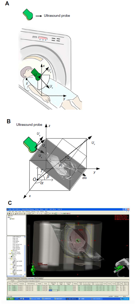 | Figure 3 Agreement between ultrasound and computed tomography beam’s eye view. |
Lastly, the US image that was not in the beam direction was registered with the CT image and was then converted into an object image of the treated target in the same beam direction as the BEV. Figure 2D shows the architecture of the proposed edge-based image registration, including offline and real time computation for both the CT and US images. The process flow includes offline calculation or real time calculation of the CT and US image. The white region could have undergone offline calculation, but the grey region had to undergo real time calculation. The present algorithm used a graphic processor unit (GPU) that could work in association with a central processor unit (CPU) to efficiently process US and CT images in real time. In this study, the GPUs were NVIDIA CUDA (Compute Unified Device Architecture) and the CPUs were Intel Pentium processors. The GPUs were GeForce GTX 470; the CPUs were Intel® Core™ 2 Duo CPU (2.40 GHz) with 4 GB of RAM. Finally, the registration experimental results in the phantom were subjected to verification of the proposed algorithm, and then we estimated an efficient and accurate registration between the CT and US images. To validate that the proposed methodology could be applied in real clinical practice, US and CT images from a hepatoma patient were registered using the same algorithm.
Results
Establishment of hybrid control with contact interactions for human commanded 6-DOF robotic manipulation
To validate the proposed hybrid control approach, experiments were performed with an US probe mounted on the end-effector of a 6-degree-of-freedom robotic manipulator to reach a set point pose commanded from the US probe held by a user. As shown in Figure 4, the exponential convergence of the proposed control approach implemented in an experimental system was successfully established. In particular, the commanded set point pose and force could be reached from any of the initial values at an exponential convergence rate.
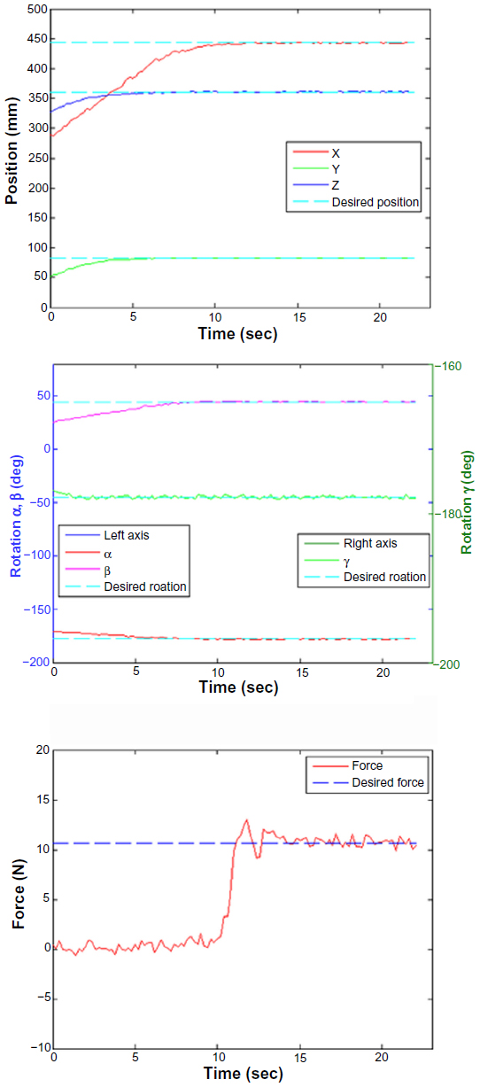 | Figure 4 The robotic processing time and task precision performance. |
Robotic processing time and task precision performance
As shown in Figure 4, the position and orientation of the US probe held by the robotic manipulator exponentially reached the desired set point pose within 13 seconds while the force successfully reached the desired value in 11 seconds. During the experiments, the proposed physician-in-the-loop visual servoing control system demonstrated effective performance on set point control. Task precision could still be guaranteed up to the image resolution even though an imprecisely calibrated vision system was employed.
Computation for US and CT image registration
The experiment was performed on CT data and US data. In the experimental data, there were 297 consecutive abdominal phantom images acquired by CT. The detailed specifications for the CT and US images were spatial resolutions of 512 (width) × 512 (height) and 1024 × 768 pixels, respectively, with a scanning interval of 0.5 mm for CT. Pixel spacing (mm/mm) was 0.5/0.5 for the CT images and 0.3539/0.3539 for the US. The dimension of captured CT images of the abdominal phantom was 512 × 512 × 297 pixels.
Results of image registration for the US and CT data
Two phantom cases were conducted to demonstrate the performance of our proposed image registration for US and CT images. Figure 5A–D shows the experimental results corresponding to phantom cases 1 and 2. Maurer et al7 suggested two error sources of measures for analyzing the accuracy of point based registration methods as follows: 1) fiducial registration error (FRE) which is the distance between corresponding fiducial points after registration and 2) target registration error (TRE) which is the distance between corresponding points other than the fiducial points after registration. The experimental results of the registration accuracy for phantom case 1 were TRE 3.3877 mm and FRE 2.4773 mm; those for phantom case 2 were TRE 3.4210 mm and FRE 5.8776 mm. The registration errors in phantom case 2 were a little worse than for case 1 because the feature points in case 2 were not clear enough to identify as in case 1. In these two phantom cases, the registration errors were within 10 mm for both FRE and TRE. Furthermore, one clinical case was added to validate that the proposed methodology could be applied in real clinical practice (Figure 5E). The registration accuracy with TRE and FRE for this clinical case was 9.85 mm and 9.35 mm, respectively. On average, the processing time for real time parts, implemented in the GPU, was around 235 milliseconds in the current stage. It implies that the registration technology can be applied in real clinical practice.
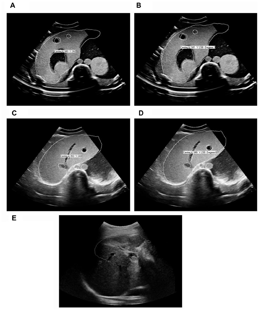 | Figure 5 Experimental results of phantom and clinical cases. |
Integration of US, CT, image registration, and generation of conceptual BEV
Figure 3 demonstrates the integration of this entire system and agreement between US and CT BEV. In Figure 3A, CT equipment and the conceptual placement of the US probe is shown with sequential registration of US and CT images. According to these procedures, a conceptual BEV integrating the tumor target noted by US/CT image registration and spatial configuration reconstructed by the RT planning system is demonstrated in Figure 3C. In comparison with conventional BEV as shown in Figure 1E, this conceptual BEV would aid treating physicians to visualize and monitor the moving target in a real time mode before, during, and after the beam-on period.
Discussion
This study successfully established a prototype of a remote controlled, dynamic tracking, real time target verification system for conformal radiotherapy. This system is composed of advancing technologies as follows: a hybrid control with contact interactions for human commanded 6-DOF robotic manipulation, remote control of a robotic handheld US probe to visualize the target in real time, and image registration for US and CT data to verify the target visualized by US.
In an attempt to visualize the target within the field of conformal radiotherapy, several practical methods have been reported. The most common modes include the implantation of radio opaque markers, such as metallic clips8 and fiducial seeds,9 as well as the application of target verification by cone beam CT scan in image guided RT.10 The clinical application of marker implantation in targets could be performed during surgery or during online imaging positioning procedures for nonsurgical settings.11 For image guided RT, the most serious concern is that the targets are visualized by digitally reconstructed structures, not the real targets during each fraction of RT.12 The target visualization system proposed in this study may spare the invasive procedures and irradiate the real moving targets by visualizing the target within each BEV. To the best of our knowledge, this is the first remote controlled target visualization system for conformal radiotherapy.
Organ motion remains an unavoidable issue in various types of RT. Fuss et al reported the development and implementation of a stereotactic US based image guided targeting device to accurately align intensity modulated radiotherapy target volumes in the upper abdomen.13 However, no real time detection of target motion was achieved. To overcome the dose uncertainty caused by organ motion, the real time and remote control of this target visualization system needs to be validated by a moving phantom to ensure adequate coverage of targets while organs move. This validation is of critical importance and is undergoing further experimentation.
The major difference between B-mode acquisition and targeting US localization system and our system is that we developed a new system using a robotic arm to control the US probe and to perform image registration to integrate US and to plan CT scan images. The US probe mounted on a robotic arm has a force sensor and the force signal can be used as feedback to the remote controller for optimization of the echogram. To avoid interference with beam delivery, the probe was placed at a non-coplanar position of the body and kept outside the beam divergence area. This arrangement made image registration of US and CT images more difficult and it has been achieved. This design could avoid X-ray exposure to the person controlling the probe during radiotherapy and thus provide a possibility to do real time target visualization by using the robotic arm.
Our initial attempt was to visualize anatomy through BEV by registering US images prior to planning CT images. For possible application in reoptimization of the beam angle prior to beam delivery, more advanced RTP systems may be needed to overcome the limitations in the current planning processing time.
In conclusion, this target visualization system may provide a remotely accessible and real time mode to visualize, verify, and justify the use of current advancing conformal RT technologies to target the targeted volumes.
Acknowledgments
This work was supported by grants MMH-TT-9912, MMH-TT-9913, MMH-TT-9914, MMH-TT-10011, MMH-TT-10012, MMH-TT-10013, MMH-TT-10110, and MMH-TT-10111 from Mackay Memorial Hospital, Taiwan, and NTUT-MMH-04, NTUT-MMH-05, NTUT-MMH-06, NTUT-MMH-100-06, NTUT-MMH-100-07, NTUT-MMH-100-08, NTUT-MMH-10110, NTUT-MMH-10111, and NTUT-MMH-10112 from National Taipei University of Technology, Taiwan.
Disclosure
The authors who have taken part in this study do not have a relationship with the manufacturers of the materials involved either in the past or present and did not receive funding from the manufacturers to carry out their research. The authors claim no conflict of interests in this work.
References
Fallavollita P, Aghaloo ZK, Burdette EC, Song DY, Abolmaesumi P, Fichnger G. Registration between ultrasound and fluoroscopy or CT in prostate brachytherapy. Med Phys. 2010;37(6):2749–2760. | |
Wilson KJ. Robotic brachytherapy of the prostate. Crit Rev Biomed Eng. 2009;37(1–2):59–106. | |
Zhu M, Salcudean SE. Real time image-based B-mode ultrasound image simulation of needles using tensor-product interpolation. IEEE Trans Med Imaging. 2011;30(7):1391–1400. | |
Fichtinger G, Burdette EC, Tanacs A, et al. Robotically assisted prostate brachytherapy with transrectal ultrasound guidance – Phantom experiments. Brachytherapy. 2006;5(1):14–26. | |
Fichtinger G, Fiene JP, Kennedy CW, et al. Robotic assistance for ultrasound-guided prostate brachytherapy. Med Image Anal. 2008;12(5):535–545. | |
Lawton CA, Hunt D, Lee WR, et al. Long-term results of a phase II trial of ultrasound-guided radioactive implantation of the prostate for definitive management of localized adenocarcinoma of the prostate (RTOG 98-05). Int J Radiat Oncol Biol Phys. 2011;81(1):1–7. | |
Maurer CR Jr, Aboutanos GB, Dawant BM, et al. Effect of geometrical distortion correction in MR on image registration accuracy. J Comput Assist Tomogr. 1996;20(4):666–679. | |
Hui A, Abi-Hanna D, Rae R, Delaney G. Use of endoscopic mucosal clips in radiotherapy planning for oesophageal carcinoma: a series of three cases. Australas Radiol. 2002;46(1):111–114. | |
Wilder RB, Chittenden L, Mesa AV, et al. A prospective study of intrafraction prostate motion in the prone vs supine position. Int J Radiat Oncol Biol Phys. 2010;77(1):165–170. | |
Moseley DJ, White EA, Wiltshire KL, et al. Comparison of localization performance with implanted fiducial markers and cone-beam computed tomography for on-line image-guided radiotherapy of the prostate. Int J Radiat Oncol Biol Phys. 2007;67(3):942–953. | |
McEntee MC, Steffey M, Dykes NL. Use of surgical hemoclips in radiation treatment planning. Vet Radiol Ultrasound. 2008;49(4):395–399. | |
Smitsmans MH, de Bois J, Sonke JJ, et al. Automatic prostate localization on cone-beam CT scans for high precision image-guided radiotherapy. Int J Radiat Oncol Biol Phys. 2005;63(4):975–984. | |
Fuss M, Salter BJ, Cavanaugh SX, et al. Daily ultrasound-based image-guided targeting for radiotherapy of upper abdominal malignancies. Int J Radiat Oncol Biol Phys. 2004;59(4):1245–1256. |
 © 2014 The Author(s). This work is published and licensed by Dove Medical Press Limited. The full terms of this license are available at https://www.dovepress.com/terms.php and incorporate the Creative Commons Attribution - Non Commercial (unported, v3.0) License.
By accessing the work you hereby accept the Terms. Non-commercial uses of the work are permitted without any further permission from Dove Medical Press Limited, provided the work is properly attributed. For permission for commercial use of this work, please see paragraphs 4.2 and 5 of our Terms.
© 2014 The Author(s). This work is published and licensed by Dove Medical Press Limited. The full terms of this license are available at https://www.dovepress.com/terms.php and incorporate the Creative Commons Attribution - Non Commercial (unported, v3.0) License.
By accessing the work you hereby accept the Terms. Non-commercial uses of the work are permitted without any further permission from Dove Medical Press Limited, provided the work is properly attributed. For permission for commercial use of this work, please see paragraphs 4.2 and 5 of our Terms.