")
Back to Journals » International Journal of Nanomedicine » Volume 10 » Issue 1
Effect of nanofiber content on bone regeneration of silk fibroin/poly(ε-caprolactone) nano/microfibrous composite scaffolds
Authors Kim BS, Park KE, Kim MH, You HK, Lee J, Park WH , Kim YJ
Received 14 August 2014
Accepted for publication 10 November 2014
Published 9 January 2015 Volume 2015:10(1) Pages 485—502
DOI https://doi.org/10.2147/IJN.S72730
Checked for plagiarism Yes
Review by Single anonymous peer review
Peer reviewer comments 4
Editor who approved publication: Professor Carlos Rinaldi
Beom Su Kim,1,2,* Ko Eun Park,3,4,* Min Hee Kim,3 Hyung Keun You,5 Jun Lee,1 Won Ho Park3
1Wonkwang Bone Regeneration Institute, Wonkwang University, Iksan, South Korea; 2Bone Cell Biotech, Daejeon, South Korea; 3Department of Advanced Organic Materials and Textile System Engineering, Chungnam National University, Daejeon, South Korea; 4Central Research Institute, Humedix, Anyang, South Korea; 5Department of Periodontology, School of Dentistry, Wonkwang University, Iksan, South Korea
*These two authors contributed equally to this work
Abstract: The broad application of electrospun nanofibrous scaffolds in tissue engineering is limited by their small pore size, which has a negative influence on cell migration. This disadvantage could be significantly improved through the combination of nano- and microfibrous structure. To accomplish this, different nano/microfibrous scaffolds were produced by hybrid electrospinning, combining solution electrospinning with melt electrospinning, while varying the content of the nanofiber. The morphology of the silk fibroin (SF)/poly(ε-caprolactone) (PCL) nano/microfibrous composite scaffolds was investigated with field-emission scanning electron microscopy, while the mechanical and pore properties were assessed by measurement of tensile strength and mercury porosimetry. To assay cell proliferation, cell viability, and infiltration ability, human mesenchymal stem cells were seeded on the SF/PCL nano/microfibrous composite scaffolds. From in vivo tests, it was found that the bone-regenerating ability of SF/PCL nano/microfibrous composite scaffolds was closely associated with the nanofiber content in the composite scaffolds. In conclusion, this approach of controlling the nanofiber content in SF/PCL nano/microfibrous composite scaffolds could be useful in the design of novel scaffolds for tissue engineering.
Keywords: silk fibroin (SF), poly(ε-caprolactone) (PCL), nanofibers, microfibers, composite scaffolds, bone regeneration
Introduction
The aim of tissue engineering and regenerative medicine is to repair and regenerate damaged tissue using scaffolds, a substitute for body tissue. Scaffolds are used to mimic the structure and biological functions of the naturally occurring extracellular matrix (ECM). ECM, the ideal model of scaffolds, plays the role of structural framework in tissue, leading to cell adhesion and the secretion of ECM protein to assist in the regeneration of damaged tissue.
Scaffolds have several requirements for use in tissue regeneration.1 First, they must have good biocompatibility to prevent inducing a foreign-body reaction after implantation. Second, it is necessary for the scaffolds to have a hydrophilic surface to facilitate cell attachment. Third, scaffolds must possess a highly open porous structure to provide mass transfer of oxygen and nutrients. In addition, good biodegradability and structural stability are needed to provide an optimal regeneration environment.1,2 The mechanical properties and degradation rate of scaffolds are decided based on the regeneration period and the type of target tissue.
Nanofibrous scaffolds have been recognized to have potential in this field because of their structural similarity to natural ECM, consisting of nanofibers ranging in diameter from 50 to 500 nm.3 The three most important methods that can be used for the fabrication of nanofibers are phase separation, self-assembly, and electrospinning.4 Phase separation can be used to obtain nanofibrous foams; however, it has many processing variables, such as the solvent, type of polymer, polymer concentration, and solvent exchange. Self-assembly has similar disadvantages, such as material limitations, and is a time-consuming process. Electrospinning is a widely used economical and simple technique for the fabrication of micro- to nanometer-size fibers from various polymers. Much of the current research has focused on the potential of electrospun fibrous scaffolds for tissue-engineering applications.5 Kurpinski et al6 improved cell adhesion through the heparin coating of an aligned nanofiber web, by controlling the rotating drum speed. Bini et al7 investigated the regeneration of nerve cells using an artificial poly(l-lactide) nerve conduit which was fabricated by electrospinning on a rotating Teflon tube. Sahoo et al8 studied woven silk scaffolds with poly(lactic-co-glycolic acid) nanofibers for connective tissue regeneration. However, electrospun nanofibrous scaffolds still have limitations for three-dimensional culturing due to their small diameter.9 Furthermore, cells cannot migrate within its dense structure due to the relatively small pore size (less than 5 μm) compared to cellular diameter (5–20 μm).6,9–12
In order to overcome these problems, newly designed nano/microfibrous composite scaffolds were fabricated through a hybrid electrospinning system (Figure 1). The hybrid electrospinning system was designed by combining melt electrospinning with traditional solution electrospinning. Traditional electrospinning systems can produce fibers with diameters of up to ~10 μm using highly concentrated polymer solutions.9 However, fiber diameters of a few micrometers are not sufficient to manufacture scaffolds with a highly porous three-dimensional structure. Therefore, in this approach, the melt-electrospinning system was used to prepare microfibers with diameters above several dozen micrometers. In the 1980s, Larrondo and St John Manley13–15 first reported the electrospinning of a molten polymer. Lyons et al16 reported a relationship between molecular weight and fiber size in this system. Zhou et al17 then obtained polylactic acid nanofibers by melt electrospinning in a guided heating chamber. Guided heating chambers control the air temperature of the space between the needle tip and collector. This process is ecofriendly, because it uses molten polymers as a spinning dope instead of polymer solutions dissolved in organic solvents.
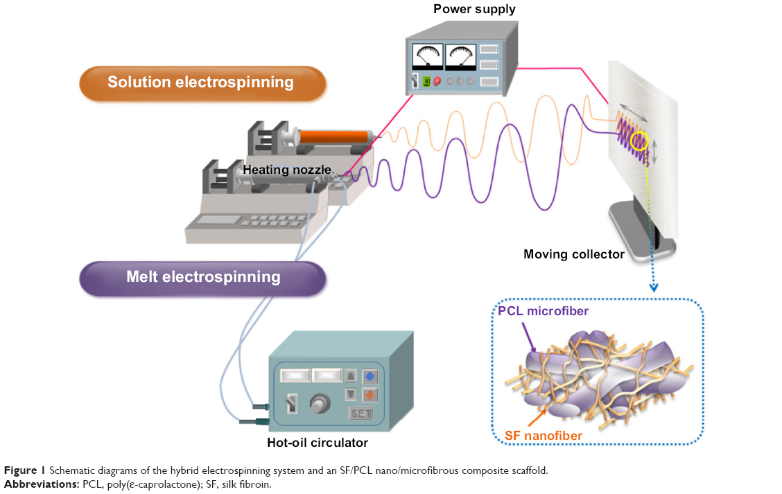 | Figure 1 Schematic diagrams of the hybrid electrospinning system and an SF/PCL nano/microfibrous composite scaffold. |
This study investigated the hybrid electrospinning of silk fibroin (SF)/poly(ε-caprolactone) (PCL) nano/microfibrous composite scaffolds with various compositions. PCL is a US Food and Drug Administration-approved synthetic polymer, and is well known for its hydrolytic and enzymatic biodegradability.18 It is a good bone-scaffolding material because it can take several years to degrade in vivo, and is biocompatible and relatively inexpensive.19 Furthermore, its low melting temperature makes it suitable for melt electrospinning.20 In this study, PCL was used as the main component in the microfibers. SF, a natural fibrous protein, gives high mechanical strength, elasticity, and softness.21,22 It is widely used in the biomedical field, due to its excellent biocompatibility.23–26 To improve the characteristics of the fibers through this study, PCL microfibers were selected for their ability to form micropores to support cell migration, while SF nanofibers were employed to mimic the structure of natural ECM for cell adhesion. The electrospun SF/PCL nano/microfibrous composite scaffolds were characterized in terms of surface morphology, porosity, mechanical properties, cell attachment, and bone regeneration.
Materials and methods
The regenerated SF sponges were obtained from degummed silk yarn in the same manner as our previous study.27 The solvent of the SF sponge, 1,1,1,3,3,3-hexafluoro-2-propanol (HFIP), was purchased from Acros Organics (Belgium) and used as received. PCL (Mn =75,000) was purchased from Dow Chemical (Tone 767; USA).
Preparation of SF/PCL nano/microfibrous composite scaffolds
To fabricate nano/microfibrous composite scaffolds, solution electrospinning and melt electrospinning were combined. Figure 1 shows a schematic of the hybrid electrospinning system and nano/microfibrous composite scaffold fabricated by hybrid electrospinning. In order to carry out melt electrospinning, PCL pellets were placed in a stainless steel syringe, and then heated to a temperature of approximately 150°C using a hot-oil circulator. The PCL melts were melt electrospun simultaneously with electrospinning of the SF solution. A stainless steel syringe with a 21 G needle was placed at a distance of 10 cm from the plate-type collector. Voltage was applied at 17 kV with a flow rate of 1 mL/h. The regenerated SF sponges were dissolved in HFIP at a concentration of 3 wt% (w/v) to prepare the SF solution for solution electrospinning. The SF solution was then electrospun on a target drum that was placed at a distance of 8 cm from the syringe tip (24 G). Several SF/PCL nano/microfibrous composite scaffolds were fabricated at different weight ratios of SF nanofiber, which were prepared by controlling the flow rate of SF solution during electrospinning (Table 1). Weight ratios were calculated from the relation between the spinning conditions of molten PCL and SF solution. The total deposition weight of melt-electrospun PCL microfibers can be acquired from the density and mass flow rate per hour of molten PCL. The weight of the electrospun SF nanofibers during deposition can be estimated from the concentration and mass flow rate per hour of the SF solution. The examined ratios of SF nanofiber to PCL microfiber were 0:100 (PCL 100), 2:98 (SF/PCL 2/98), 4:96 (SF/PCL 4/96), 6:94 (SF/PCL 6/94), and 8:92 (SF/PCL 8/92) (w/w). The SF/PCL nano/microfibrous composite scaffolds were treated with water vapor at 40°C for 4 hours to cross-link the regenerated SF nanofibers.28,29 The water vapor-treated SF/PCL nano/microfibrous scaffolds were then washed with distilled water for 1 hour and dried in a vacuum for 24 hours at room temperature.
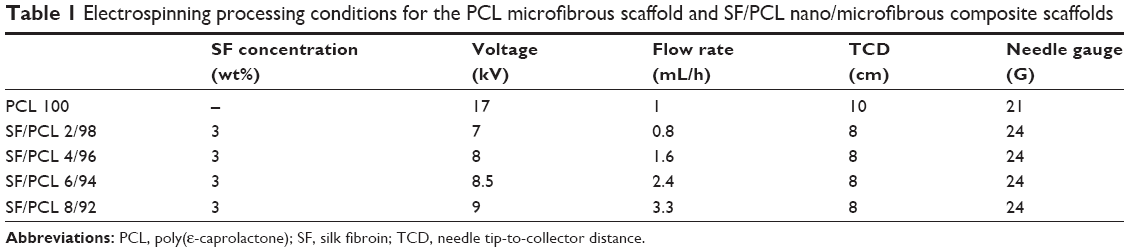 | Table 1 Electrospinning processing conditions for the PCL microfibrous scaffold and SF/PCL nano/microfibrous composite scaffolds |
Characterization of composite scaffolds
The surface morphology and pore structure of the SF/PCL nano/microfibrous composite scaffolds before and after water-vapor treatment were observed with a field-emission scanning electron microscope (SEM; JSM-7000F; JEOL, Japan). Prior to the observation, the specimens were coated with platinum through ion sputtering for a few seconds. The average diameter and diameter distributions were obtained by analyzing the SEM images with a customized image-analysis program (Scope Eye II; TDI, South Korea). The pore properties of the SF/PCL nano/microfibrous composite scaffolds were measured with a mercury porosimeter (AutoPore IV 9520; Micrometrics, USA). The tensile properties were measured ten times on a tensile tester (model 4467; Instron, USA), according to the ASTM D638-10 standard test method. The dog-bone-shaped specimens were characterized with an elongation speed of 10 mm/min and a load cell of 50 N. Ten independent measurements for each sample were averaged, except maximum and minimum value.
Plasma treatment
Before the cell-culture and animal tests, the PCL microfibrous scaffold and SF/PCL nano/microfibrous composite scaffolds were treated with NH3 plasma using a MiniPlasma station (Plasmart, South Korea) to increase their hydrophilicity.30,31 The chamber was evacuated to less than 10 mTorr before it was filled with NH3 (100 mL/min), followed by the generation of glow-discharged plasma (20 W) for 50 seconds.
Cell culture
To obtain human mesenchymal stem cells (hMSCs), bone marrow was aspirated from the alveolar bone of patients during oral surgery. All patient participation was approved by the Institute Research Review Board in the Department of Periodontology at Wonkwang University Dental Hospital. The properties of the hMSCs were discussed in our previous study.32 The cells were cultured in α-modified Eagle’s medium (Gibco, USA) containing 10% fetal bovine serum and 1% antibiotics (penicillin G 10,000 units/mL, amphotericin B 25 μg/mL; Gibco) and incubated at 37°C in a 5% CO2 environment. In this study, cells passaged three to six times were used, and the culture medium was changed every 2 days. PCL 100, SF/PCL 2/98, and SF/PCL 6/94 scaffolds were cut into small rounds of 5 mm, 12 mm, and 30 mm in diameter, and these specimens were transferred to 96-well, 24-well, and six-well tissue-culture dishes, respectively. All specimens were sterilized with ethylene oxide gas. In this study, the 5 mm rounds were used for the 3-(4,5-dimethylthiazol-2- yl)-5-(3-carboxymethoxyphenyl)-2-(4-sulfophenyl)-2H-tetrazolium (MTS) assay, and the 12 mm rounds were used for Live/Dead and alizarin red sulfate (AR-S) staining.
MTS assay
Proliferation of the cells attached to and subsequently grown on the scaffold was assessed using CellTiter96® Aqueous One solution (Promega, USA). Briefly, hMSCs were seeded on sterilized specimens 5 mm in diameter in a 96-well culture dish. For measurement at the indicated intervals, 25 μL of MTS reagent was added to each well and incubated for 4 hours. Absorbance was measured at 490 nm on an enzyme-linked immunosorbent assay reader (SpectraMax M3; Molecular Devices, USA).
Live/Dead staining
To assess cell viability, a Live/Dead® viability/cytotoxicity kit (Molecular Probes, UK) was used. Briefly, hMSCs were seeded on sterilized specimens 12 mm in diameter in a 24-well culture dish. After 5 days of culturing, the scaffolds were washed with phosphate-buffered saline for 30 minutes to remove the phenol red and serum, and then incubated in Live/Dead viability/cytotoxicity solution. Healthy cells stained with calcein acetoxymethyl (AM; 0.05%) were seen in green, while the ethidium homodimer-1 (EthD-1, 0.2%)-stained nuclei of the dead cells appeared in red. After staining, the sample was observed under a fluorescence microscope (DM IL LED Fluo; Leica, Germany).
Cell infiltration
After 5 days of cultivation, the scaffolds cultured with cells were embedded in optimum cutting temperature compound (TissueTek, USA), cut into sections 10 mm in thickness, and fixed onto microscope slides. The sections were fixed in 10% formalin, and then stained with hematoxylin to visualize cell infiltration into the scaffold.
Osteoblast induction
To induce osteoblast differentiation of the hMSCs, the cells were treated with osteogenic differentiation stimulant (OS): 10 mM β-glycerophosphate (Sigma, USA), 50 μg/mL ascorbic acid (Sigma), and 0.1 mM dexamethasone (Sigma). The OS treatment was repeated every 2 days during osteoblast induction.
AR-S staining
Calcium accumulation was determined using AR-S (Sigma) staining. The hMSCs were cultured on scaffolds in a 24-well culture dish for 19 days with continuous OS treatment. Extracellular mineralization was induced by adding 4 mM NaHPO4 (Sigma), then the medium was removed and cells were rinsed with PBS. Fixation was established with ice-cold 70% ethanol for 1 hour at 4°C. The ethanol was then removed, and the cells were stained for 10 minutes at room temperature with 40 mM AR-S solution. The stained portions were observed under a fluorescence microscope at light source (DM IL LED Fluo).
Quantitative real-time PCR
Total messenger RNA (mRNA) was isolated from culture hMSCs on scaffolds and treated with OS for 5 days, and complementary deoxyribonucleic acid (cDNA) was transcribed with reverse transcriptase (Invitrogen) and oligodeoxythymidine primers. The cDNA was amplified with TaqMan universal polymerase chain reaction (PCR) master mix (Applied Biosystems, USA) and primers and TaqMan probe sets for alkaline phosphatase (ALP; Hs01029144_m1), osteocalcin (OC; Hs01587814_g1), and runt-related transcription factor 2 (Runx2; Hs00231692_m1) were purchased from Applied Biosciences. All TaqMan PCR was performed using StepOne Plus real-time PCR system (Applied Biosystems). Amount of cDNAs were normalized to that of 18S ribosomal RNA.
Animal experiments
Six adult (over 3 months old) male New Zealand White rabbits (2.5–3.0 kg) were anesthetized with an intramuscular dose of ketamine (35 mg/kg; Yuhan, South Korea) and xylazine (5 mg/kg; Bayer Korea, South Korea), and then local anesthesia was provided using a 2% lidocaine solution. After proper preparation, three separated circular calvarial defects were made using a trephine with an outer diameter of 6 mm on a slow-speed electric hand piece while applying 0.9% physiologic saline irrigation. Each scaffold was implanted in the bone defects. One of the defects was used as a control, without implantation. The healing process was observed 1, 2, 4, and 8 weeks postimplantation, and the defects together with the surrounding bone were dissected from the host bone. Specimens were removed and placed in phosphate-buffered 4% paraformaldehyde solution (pH 7.2) inside a 4°C refrigerator for fixation (7–10 days).
Histological analysis
The specimens were decalcified with 8% formic acid/8% HCl before being dehydrated in a graded alcohol series (70%–100%) and then embedded in paraffin. The specimens were cut into 5 μm sections (HM 325; Microm, Germany), and five sections from the central part of each sample were stained with hematoxylin and eosin (H&E) and Goldner’s Masson trichrome. New bone formation and inflammatory response were then examined under a light microscope. The system included a digital camera (DFC-480; Leica) mounted on a light microscope (DMR; Leica). Furthermore, to quantify the amount of new bone formation, the bone area was pseudocolored using Adobe Photoshop CS2, and the area was measured using Image Pro Plus software (Media Cybernetics, USA).
Statistical analysis
All experiments were performed at least in triplicate. The values are expressed as means ± standard deviation, and statistical analysis was performed by one-way analysis of variance followed by Student’s t-test using Prism version 5.3 software (GraphPad Software, USA). P<0.05 was considered statistically significant.
Results and discussion
Morphology of SF/PCL nano/microfibrous composite scaffolds
When using nanofibrous scaffolds, it is difficult to manufacture three-dimensional structures due to the small diameter of the fibers. Therefore, there is limited cell migration to the center of the scaffold because the inside pores are too small. In contrast, microfibrous scaffolds can easily make a three-dimensional structure, but cell adhesion and proliferation on the scaffold become more difficult owing to the decrease of specific surface area caused by the large pore sizes.33 Therefore, composite scaffolds containing a combination of nanofibers and microfibers were designed in this study (Figure 1). PCL microfibers play a role in the skeleton of composite scaffolds, facilitating cell infiltration by the formation of large pores. Cells can effectively adhere and grow on the composite scaffolds, because the SF nanofibers provide an ECM-like environment. The ratios of SF nanofibers and PCL microfibers were controlled by a flow-rate change of the SF solution during electrospinning. After accumulation for several hours, scaffolds with a thickness of 2–3 mm were prepared by hybrid electrospinning. Figure S1 shows the SEM images and fiber distributions of SF of the nanofibers with various electrospinning conditions, in accordance with Table 1. Despite changes in the electrospinning conditions, the average diameter of the SF/PCL 2/98 nano/microfibrous composite scaffold was similar to that of the SF/PCL 4/96 and SF/PCL 6/94 nano/microfibrous composite scaffolds. However, the SF/PCL 8/92 nano/microfibrous composite scaffold had the smallest average diameter with the largest fiber distribution, since the applied voltage was increased greatly along with the flow rate. The surface morphologies of the PCL microfibrous scaffold and SF/PCL nano/microfibrous composite scaffolds with various SF-nanofiber contents can be seen in Figure 2. It was found that the SF nanofibers and PCL microfibers were randomly deposited on the collector, and the micropores formed by PCL microfibers were split into smaller sizes by the electrospun SF nanofibers. During electrospinning, the electrostatic attraction between the needle tip and the collector was influenced by the applied voltage and the needle tip-to-collector distance (TCD). In this system, the TCD was decreased by the deposition of PCL microfibers on the collector with spinning time. To increase the SF-nanofiber content incorporated in the composite scaffolds, the applied voltage and flow rate were increased. For the same reasons, a higher quantity of SF nanofibers was deposited onto the PCL microfibers parallel to their axis. Therefore, the micropores of the SF/PCL nano/microfibrous composite scaffolds were not blocked despite an increase of SF included in the nanofibers.
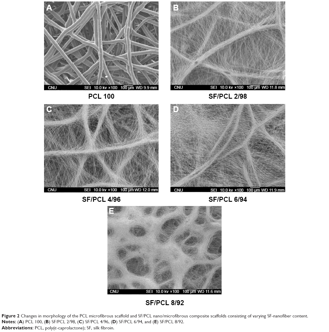 | Figure 2 Changes in morphology of the PCL microfibrous scaffold and SF/PCL nano/microfibrous composite scaffolds consisting of varying SF-nanofiber content. |
Stabilization of SF/PCL nano/microfibrous composite scaffolds
Water-vapor treatment is necessary for the stabilization of water-soluble SF nanofibers fabricated from regenerated SF solution. The stabilization of SF nanofibers using water vapor was reported in our previous studies.28,29 SF/PCL nano/microfibrous scaffolds were immersed in distilled water for 1 hour after water-vapor treatment, and then dried to observe changes in surface morphology (Figure S2). No morphological changes were observed in Figure S2 in comparison to Figure 2. It was found that water-vapor treatment effectively led to the stabilization of the water-soluble SF nanofibers.
Pore properties
The properties of the pores in the SF/PCL nano/microfibrous composite scaffolds were analyzed through mercury porosimetry. Figure 3 shows the pore distributions of the SF/PCL nano/microfibrous composite scaffolds. It can be seen that the number of small pores in the SF/PCL nano/microfibrous composite scaffolds increased with the increment of SF-nanofiber content, as the deposited SF nanofibers divided the large pores originally formed by the PCL microfibers into smaller pores. This result is consistent with the SEM images in Figure 2. The porosity of the PCL microfibrous scaffold and SF/PCL nano/microfibrous composite scaffolds was close to 80%, irrespective of the SF-nanofiber content. These results could be explained in terms of the high surface area-to-volume ratio of the nanofibers. Therefore, increasing amounts of SF nanofiber in the composite scaffolds did not affect porosity. These results indicated that a three-dimensional scaffold with highly porous structure was successfully fabricated.
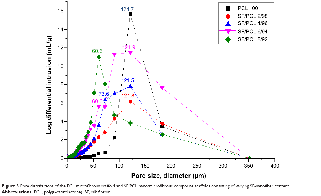 | Figure 3 Pore distributions of the PCL microfibrous scaffold and SF/PCL nano/microfibrous composite scaffolds consisting of varying SF-nanofiber content. |
Mechanical properties
The tensile properties were measured to analyze the mechanical properties of the SF/PCL nano/microfibrous composite scaffolds. The tensile properties are shown in Table 2 and Figure 4. The tensile strength of the composite scaffolds, excluding SF/PCL 8/92, was lower than that of the PCL microfibrous scaffold, and gradually decreased with increasing SF-nanofiber content in the composite scaffolds, due to poor interaction between the SF nanofiber and PCL microfiber. In the case of the SF/PCL 8/92 nano/microfibrous composite scaffold, the SF nanofibers deposited onto the PCL microfibers were physically connected to the PCL microfibers, allowing SF-nanofiber membranes formed between the PCL microfibrous layers to affect tensile strength. For these reasons, the SF/PCL 8/92 scaffolds had the highest tensile strength. The tensile modulus decreased with increasing SF-nanofiber content in the composite scaffolds, because the SF nanofibers were more flexible than PCL microfiber.
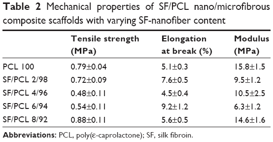 | Table 2 Mechanical properties of SF/PCL nano/microfibrous composite scaffolds with varying SF-nanofiber content Abbreviations: PCL, poly(ε-caprolactone); SF, silk fibroin. |
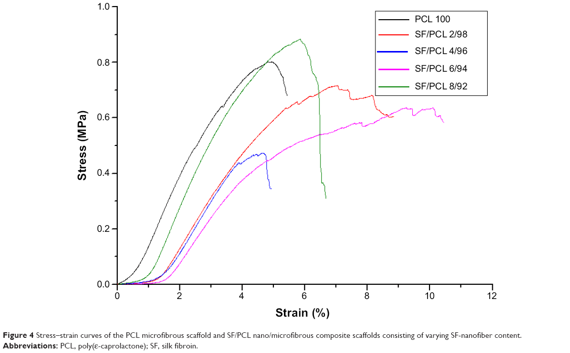 | Figure 4 Stress–strain curves of the PCL microfibrous scaffold and SF/PCL nano/microfibrous composite scaffolds consisting of varying SF-nanofiber content. |
In vitro cell proliferation
Various cell tests were conducted on the PCL microfibrous scaffold and SF/PCL nano/microfibrous composite scaffolds to determine in vitro cell cytocompatibility. The proliferation of hMSCs on the PCL microfibrous scaffold and the SF/PCL nano/microfibrous composite scaffolds was evaluated on day 1, 3, 6, and 12 using an MTS assay. Figure 5 shows the MTS results at 1, 3, 6, and 12 days after cell seeding. The MTS results showed that cell proliferation of the SF/PCL 2/98 (0.162±0.015) and SF/PCL 6/94 (0.139±0.007) nano/microfibrous composite scaffolds was significantly higher than that on the PCL microfibrous scaffold (0.021±0.006) at 1 day of cell culture (P<0.05). The result indicated that the addition of SF nanofibrous affects initial cell adhesion. In addition, the cells gradually grew well from day 3 to 12 on both of the SF/PCL 2/98 and SF/PCL 6/94 nano/microfibrous composite scaffolds, and the optical densities of the SF/PCL nano/microfibrous composite scaffolds were higher than that of the PCL microfibrous scaffold during the period of cell culture. These data indicated that cell proliferation on the scaffolds was clearly influenced by SF nanofiber in the microfibrous composite scaffolds.
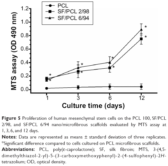 | Figure 5 Proliferation of human mesenchymal stem cells on the PCL 100, SF/PCL 2/98, and SF/PCL 6/94 nano/microfibrous scaffolds evaluated by MTS assay at 1, 3, 6, and 12 days. |
Figure 6 shows SEM images of the hMSCs on the composite scaffolds after 3 days of culturing. Cell clusters were not observed in the PCL microfibrous scaffold, as its pore size was too large. In the case of the composite scaffolds, hMSCs adhered well and formed cell clusters, because smaller pores were made by the deposition of electrospun SF nanofibers on the PCL microfibers. Furthermore, hMSCs were elongated and spread on the nanofibrous surface of the composite scaffolds.
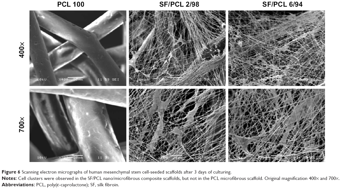 | Figure 6 Scanning electron micrographs of human mesenchymal stem cell-seeded scaffolds after 3 days of culturing. |
In vitro cell viability and cytotoxicity
The viability/cytotoxicity of hMSCs on different types of scaffolds with varying SF content was visualized with fluorescence microscopy (Figure 7). Calcein AM and EthD-1 were used as Live/Dead reagents. The live cells were stained with calcein AM to emit green fluorescence under a fluorescence microscope. Dead cells, labeled with EthD-1, appeared in red. As seen in Figure 7, many living cells were stained on the SF/PCL nano/microfibrous scaffolds after 5 days of culturing. However, living cells were not observed on the PCL microfibrous scaffolds, due to the large size of the pores in comparison to the size of the seeded cells, as previously described. The cell viability of SF/PCL nano/microfibrous composite scaffolds was higher than the PCL microfibrous scaffold. However, there was negligible difference between the composite scaffolds. These results indicated that cell viability on the scaffolds was significantly influenced by existence of SF nanofibers in the composite scaffolds. Furthermore, EthD-1 staining revealed that all three types of composite scaffolds were not cytotoxic.
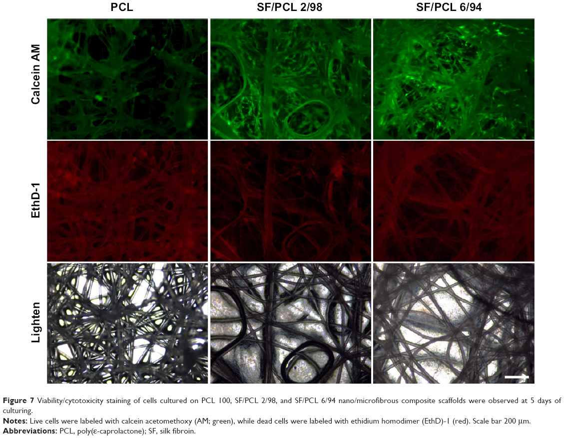 | Figure 7 Viability/cytotoxicity staining of cells cultured on PCL 100, SF/PCL 2/98, and SF/PCL 6/94 nano/microfibrous composite scaffolds were observed at 5 days of culturing. |
In vitro cell infiltration
Generally, cell growth occurs on the surface of electrospun nanofibrous scaffolds,6,10–12 while cells have difficulty growing on microfibrous scaffolds consisting of pores of size larger than the cells.33 Cross-sectional images were measured to compare the ability of cells to infiltrate the PCL microfibrous scaffold with the ability to infiltrate the SF/PCL nano/microfibrous composite scaffolds. Figure 8 shows a cross section of a PCL microfibrous scaffold and the SF/PCL nano/microfibrous composite scaffolds after 5 days of culturing with the hMSCs. Cells penetrating the PCL microfibrous scaffold with a large pore size were rarely observed. This result agreed well with the previous test of cell viability. In contrast, the SF/PCL nano/microfibrous composite scaffolds exhibited high infiltration and ingrowth of hMSCs. These results indicated that the nanofibers in the composite scaffolds played a positive role in cell growth and infiltration.
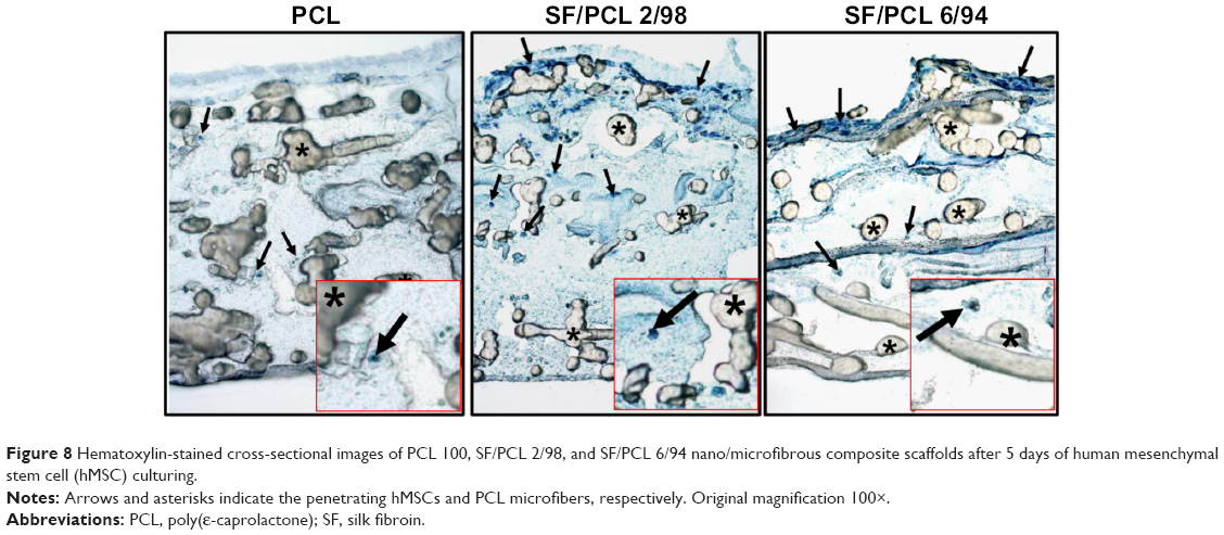 | Figure 8 Hematoxylin-stained cross-sectional images of PCL 100, SF/PCL 2/98, and SF/PCL 6/94 nano/microfibrous composite scaffolds after 5 days of human mesenchymal stem cell (hMSC) culturing. |
Determination of osteoblast differentiation
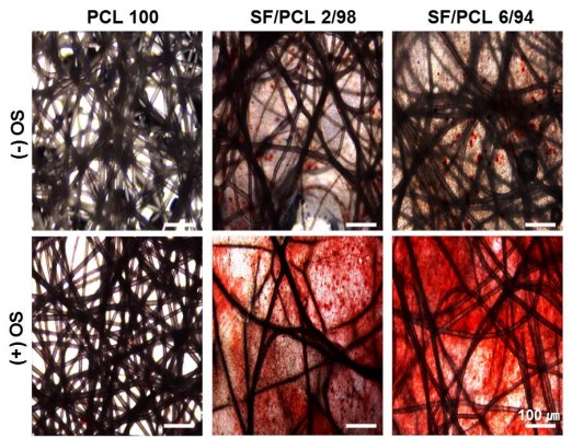
Before the in vivo bone-regeneration analysis, in vitro mineralization ability of three scaffold types was determined by AR-S staining, which binds selectively to calcium deposits. Commonly, human MSCs can differentiate into osteoblasts, which produce calcium deposits. Therefore, the results of AR-S staining indicate the osteogenic differentiation capacity of hMSCs seeded on the scaffolds. In addition, OS treatment was used to promote the osteogenic differentiation of hMSCs in this study. Figure 9 shows the results of AR-S staining for the three scaffold types after 21 days of culturing with hMSCs. As shown in the figure, SF/PCL 6/94 nano/microfibrous composite scaffolds appeared to have the most calcium-rich phase in comparison to the PCL microfibrous scaffold and the SF/PCL 2/98 nano/microfibrous composite scaffold.
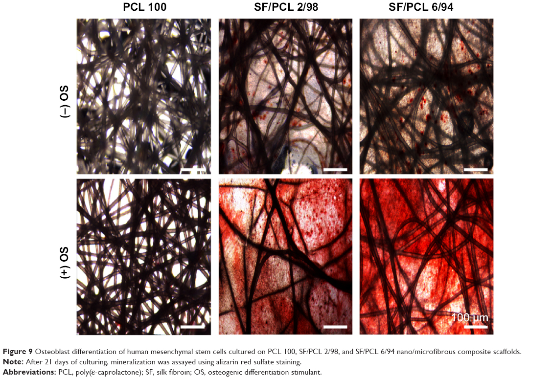 | Figure 9 Osteoblast differentiation of human mesenchymal stem cells cultured on PCL 100, SF/PCL 2/98, and SF/PCL 6/94 nano/microfibrous composite scaffolds. |
During cellular differentiation of osteoblasts, several genes, such as ALP, BGLAP (OC), and RUNX2 were required. ALP is one of the most commonly used markers of osteogenesis, and reflects the proportion of osteogenic differentiation.34 OC is a bone-specific protein that represents a good early marker for in vitro osteogenic differentiation.35 In addition, Runx2 plays a key role in osteoblast differentiation.36 Therefore, to confirm osteoblast differentiation, ALP, OC, and Runx2 were used as indicative markers for osteoblast differentiation. In this study, the gene-expression level of ALP was significantly increased in both the SF/PCL 2/98 (3.3-fold) and SF/PCL 6/94 (3.6-fold) nano/microfibrous composite scaffolds when compared with that cultured on the PCL microfibrous scaffold. The gene-expression level of OC also increased in both the SF/PCL 2/98 (1.8-fold) and the SF/PCL 6/94 (1.7-fold) nano/microfibrous composite scaffold. Furthermore, the gene expression of Runx2 was also increased in both the SF/PCL 2/98 (4.4-fold) and SF/PCL 6/94 (4.7-fold) nano/microfibrous composite scaffold. However, there was no significant difference between the SF/PCL 2/98 and SF/PCL 6/94 nano/microfibrous composite scaffolds (P>0.05) (Figure 10). These results indicate that SF nanofiber can provide the environment for improved osteoblast differentiation.
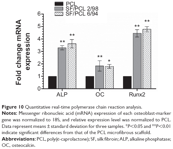 | Figure 10 Quantitative real-time polymerase chain reaction analysis. |
In vivo bone regeneration
To investigate the in vivo bone-regeneration ability of the PCL microfibrous scaffold and the SF/PCL nano/microfibrous composite scaffolds, the scaffolds were implanted in the calvarial defects of rabbits. Figure 11 shows low-magnification images of the H&E-stained histological sections at 1, 2, 4 and 8 weeks postimplantation. The control group had no implants. As seen in the figure, in vivo bone regeneration was observed to progress from the defect edge toward the center. At 1 week, all groups showed an inflammatory reaction, formation of loose connective tissue, and weak new bone formation at the defect edges. At 2 weeks, new bone was formed at the defect edges of all groups, with induction of blood vessels into the defect sites. The control group (empty defect) was still filled with dense connective fibrous tissue after 4 weeks. However, in the case of SF/PCL 2/98 nano/microfibrous composite scaffolds, newly formed bone was observed at the defect center after 4 weeks. The SF/PCL 6/94 nano/microfibrous composite scaffolds demonstrated higher angiogenesis than the other groups. At 8 weeks postimplantation, bone regeneration was significantly induced by the SF/PCL nano/microfibrous composite scaffolds compared to both the control group and PCL microfibrous scaffold group. Notably, fully regenerated bone was observed in those implanted with SF/PCL 6/94 nano/microfibrous composite scaffolds. Figure S3 shows high-magnification images of the H&E-stained histological sections in the edges of host bone with different regeneration conditions. As shown in the figure, all implantation groups had higher angiogenesis and new bone formation than the control group in the calvarial defect edges after 2 weeks. At 8 weeks postimplantation, the boundary between host bone and newly formed bone could not be distinguished in any of the implantation groups. In particular, the matured new bone of lamellar structures was formed in the SF/PCL 6/94 composite scaffold group at 8 weeks. Figure 12 shows cross-sectional images of the center of the defect margin after Goldner’s Masson trichrome stain. During the first 2 weeks after implantation, inflammatory cells existed in the center of the defect margin. The center of the defect margin was then filled with connective tissue. On the other hand, inflammation reactions disappeared and new bones were formed in the center of the defect margin at 4 weeks postimplantation. At 8 weeks, the newly formed bones in the SF/PCL 6/94 nano/microfibrous composite scaffolds were difficult to distinguish from the host bone. Bone regeneration and angiogenesis at the center of the defect margin were markedly increased with the use of SF/PCL composite scaffolds compared to both the control and the PCL microfibrous scaffold during the total regeneration period. In addition, as shown in Figure 13, the quantitative analysis of new bone area showed that a large amount of new bone was formed in the SF/PCL 6/94 nano/microfibrous composite scaffold-implanted group. These quantitative data were similar to those found by histological slide images. Consequently, these results indicated that a composite structure consisting of nanofibers and microfibers plays a positive role in bone regeneration, helping to form new bone in defect sites. As a result of the in vivo bone-regeneration tests, it was found that nano/microfibrous composite scaffolds have the potential for use in bone-regeneration applications.
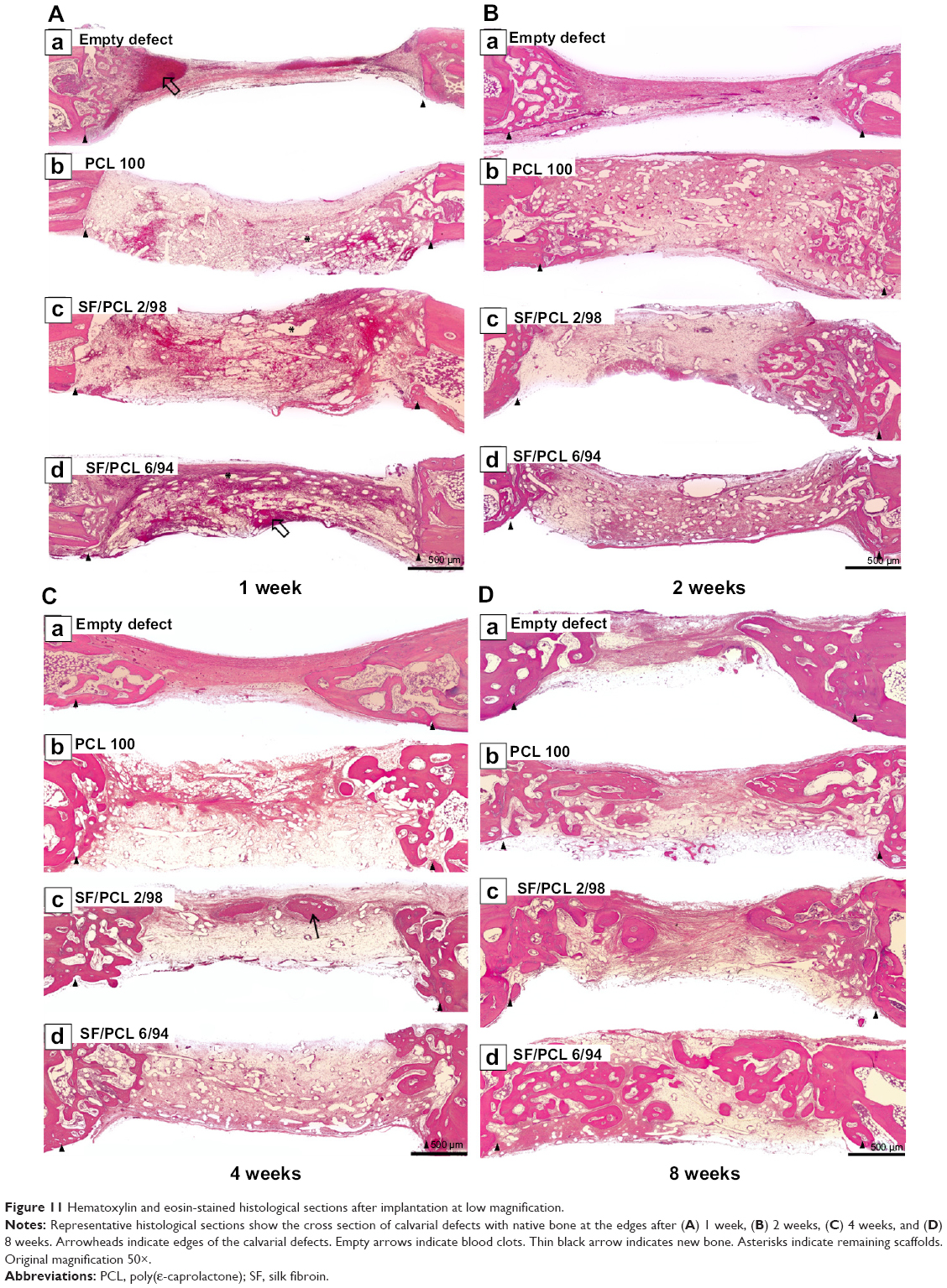 | Figure 11 Hematoxylin and eosin-stained histological sections after implantation at low magnification. |
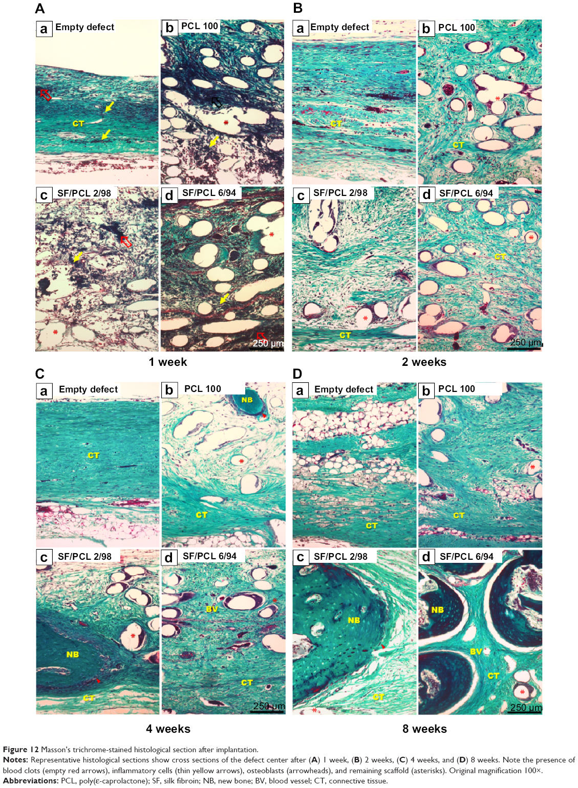 | Figure 12 Masson’s trichrome-stained histological section after implantation. |
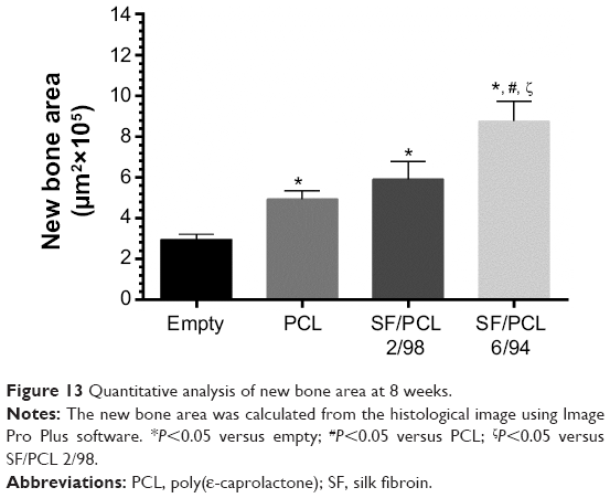 | Figure 13 Quantitative analysis of new bone area at 8 weeks. |
In this study, SF/PCL nano/microfibrous composite scaffold were fabricated via hybrid electrospinning method. The SF/PCL nano/microfibrous composite scaffolds were prepared by different amounts of inclusion of SF nanofiber onto the PCL microfiber. The increment of SF nanofiber content in the composite scaffolds led to a decrease in pore size. Results from MTS assay, SEM images of hMSC-seeded scaffolds, and viability tests indicated that it had no significant difference on cell growth and pore size in the case of composite scaffolds. However, composite scaffolds are excellent than PCL microfibrous scaffolds. This means that small pores formed by SF nanofibers in composite scaffolds have a positive effect on cell growth. Therefore, the SF/PCL nano/microfibrous composite scaffold provides a suitable environment for hMSC proliferation, adhesion, and differentiation into osteoblasts in vitro. In addition, the SF/PCL nano/microfibrous composite scaffolds stimulated new bone formation in rabbit calvarial defect model in vivo. Our findings suggest that SF/PCL nano/microfibrous composite scaffolds have potential for use in bone-regeneration fields.
Acknowledgment
This research was supported by the Nuclear R&D program (NRF-2012M2A2A6035747) through the National Research Foundation, funded by the Ministry of Science, ICT and Future Planning, South Korea.
Disclosure
The authors report no conflicts of interest in this work.
References
Yang S, Leong KF, Du Z, Chua CK. The design of scaffolds for use in tissue engineering. Part I. Traditional factors. Tissue Eng. 2001;7(6): 679–689. | ||
Lu Q, Ganesan K, Simionescu DT, Vyavahare NR. Novel porous aortic elastin and collagen scaffolds for tissue engineering. Biomaterials. 2004; 25(22):5227–5237. | ||
Barnes CP, Sell SA, Boland ED, Simpson DG, Bowlin GL. Nanofiber technology: designing the next generation of tissue engineering scaffolds. Adv Drug Deliv Rev. 2007;59(14):1413–1433. | ||
Ashammakhi N, Ndreu A, Yang Y, Ylikauppila H, Nikkola L. Nanofiber-based scaffolds for tissue engineering. Eur J Plast Surg. 2008;35(2): 135–149. | ||
Yu DG, Zhu LM, White K, Branford-White C. Electrospun nanofiber-based drug delivery systems. Health. 2009;1(2):67–75. | ||
Kurpinski KT, Stephenson JT, Janairo RR, Lee H, Li S. The effect of fiber alignment and heparin coating on cell infiltration into nanofibrous PLLA scaffolds. Biomaterials. 2010;31(13):3536–3542. | ||
Bini TB, Gao S, Tan TC, et al. Electrospun poly(L-lactide-co-glycolide) biodegradable polymer nanofibre tubes for peripheral nerve regeneration. Nanotechnology. 2004;15(11):1459–1464. | ||
Sahoo S, Toh SL, Goh JC. PLGA nanofiber-coated silk microfibrous scaffold for connective tissue engineering. J Biomed Mater Res B Appl Biomater. 2010;95(1):19–28. | ||
Kim SJ, Jang DH, Park WH, Min BM. Fabrication and characterization of 3-dimensional PLGA nanofiber/microfiber composite scaffolds. Polymer. 2010;51(6):1320–1327. | ||
Leong MF, Chan WY, Chian KS, Rasheed MZ, Anderson JM. Fabrication and in vitro and in vivo cell infiltration study of a bilayered cryogenic electrospun poly(D,L-lactide) scaffold. J Biomed Mater Res A. 2010; 94(4):1141–1149. | ||
Cao H, McHugh K, Chew SY, Anderson JM. The topographical effect of electrospun nanofibrous scaffolds on the in vivo and in vitro foreign body reaction. J Biomed Mater Res A. 2010;93(3):1151–1159. | ||
Leong MF, Rasheed MZ, Lim TC, Chian KS. In vitro cell infiltration and in vivo cell infiltration and vascularization in a fibrous, highly porous poly(D,L-lactide) scaffold fabricated by cryogenic electrospinning technique. J Biomed Mater Res A. 2009;91(1):231–240. | ||
Larrondo L, St John Manley R. Electrostatic fiber spinning from polymer melts. I. Experimental observations on fiber formation and properties. J Polym Sci Polym Phys Ed. 1981;19(6):909–920. | ||
Larrondo L, St John Manley R. Electrostatic fiber spinning from polymer melts. II. Examination of the flow field in an electrically driven jet. J Polym Sci Polym Phys Ed. 1981;19(6):921–932. | ||
Larrondo L, St John Manley R. Electrostatic fiber spinning from polymer melts. III. Electrostatic deformation of a pendant drop of polymer melt. J Polym Sci Polym Phys Ed. 1981;19(6):933–940. | ||
Lyons J, Li C, Ko F. Melt-electrospinning part I: processing parameters and geometric properties. Polymer. 2004;45(22):7597–7603. | ||
Zhou H, Green TB, Joo YL. The thermal effects on electrospinning of polylactic acid melts. Polymer. 2006;47(21):7497–7505. | ||
Sant S, Hwang CM, Lee SH, Khademhosseini A. Hybrid PGS-PCL microfibrous scaffolds with improved mechanical and biological properties. J Tissue Eng Regen Med. 2011;5(4):283–291. | ||
Heo SJ, Kim SE, Wei J, et al. Fabrication and characterization of novel nano- and micro-HA/PCL composite scaffolds using a modified rapid prototyping process. J Biomed Mater Res A. 2009;89(1):108–116. | ||
Persenaire O, Alexandre M, Degée P, Dubois P. Mechanisms and kinetics of thermal degradation of poly(ε-caprolactone). Biomacromolecules. 2001;2(1):288–294. | ||
Chen C, Chuanbao C, Xilan M, Yin T, Hesun Z. Preparation of non-woven mats from all-aqueous silk fibroin solution with electrospinning method. Polymer. 2006;47(18):6322–6327. | ||
Wang M, Jin HJ, Kaplan DL, Rutledge GC. Mechanical properties of electrospun silk fibers. Macromolecules. 2004;37(18):6856–6864. | ||
Kim KH, Jeong L, Park HN, et al. Biological efficacy of silk fibroin nanofiber membranes for guided bone regeneration. J Biotechnol. 2005; 120(3):327–339. | ||
Kundu B, Rajkhowa R, Kundu SC, Wang X. Silk fibroin biomaterials for tissue regeneration. Adv Drug Deliv Rev. 2013;65(4):457–470. | ||
Wenk E, Merkle HP, Meinel L. Silk fibroin as a vehicle for drug delivery applications. J Control Release. 2011;150(2):128–141. | ||
Zhang K, Mo X, Huang C, He C, Wang H. Electrospun scaffolds from silk fibroin and their cellular compatibility. J Biomed Mater Res A. 2010; 93(3):976–983. | ||
Park KE, Jung SY, Lee SJ, Min BM, Park WH. Biomimetic nanofibrous scaffolds: preparation and characterization of chitin/silk fibroin blend nanofibers. Int J Biol Macromol. 2006;38(3–5):165–173. | ||
Jeong L, Lee KY, Liu JW, Park WH. Time-resolved structural investigation of regenerated silk fibroin nanofibers treated with solvent vapor. Int J Biol Macromol. 2006;38(2):140–144. | ||
Min BM, Jeong L, Lee KY, Park WH. Regenerated silk fibroin nanofibers: water vapor-induced structural changes and their effects on the behavior of normal human cells. Macromol Biosci. 2006;6(4):285–292. | ||
Park H, Lee JW, Park KE, Park WH, Lee KY. Stress response of fibroblasts adherent to the surface of plasma-treated poly(lactic-co-glycolic acid) nanofiber matrices. Colloid Surf B Biointerfaces. 2010;77(1):90–95. | ||
Park KE, Lee KY, Lee SJ, Park WH. Surface characteristics of plasma-treated PLGA nanofibers. Macromol Symp. 2007;249–250(1):103–108. | ||
Kim BS, Kim YC, Zadeh H, et al. Effects of the dichloromethane fraction of Dipsaci Radix on the osteoblastic differentiation of human alveolar bone marrow-derived mesenchymal stem cells. Biosci Biotechnol Biochem. 2011;75(1):13–19. | ||
Murphy CM, O’Brien FJ. Understanding the effect of mean pore size on cell activity in collagen-glycosaminoglycan scaffolds. Cell Adh Migr. 2010;4(3):377–381. | ||
Bianco P, Riminucci M, Bonucci E, Termine JD, Robey PG. Bone sialoprotein (BSP) secretion and osteoblast differentiation: relationship to bromodeoxyuridine incorporation, alkaline phosphatase, and matrix deposition. J Histochem Cytochem. 1993;41(2):183–191. | ||
Nakamura A, Dohi Y, Akahane M, et al. Osteocalcin secretion as an early marker of in vitro osteogenic differentiation of rat mesenchymal stem cells. Tissue Eng Part C Methods. 2009;15(2):169–180. | ||
Banerjee C, McCabe LR, Choi JY, et al. Runt homology domain proteins in osteoblast differentiation: AML3/CBFA1 is a major component of a bone-specific complex. J Cellular Biochem. 1997;66(1):1–8. |
Supplementary materials
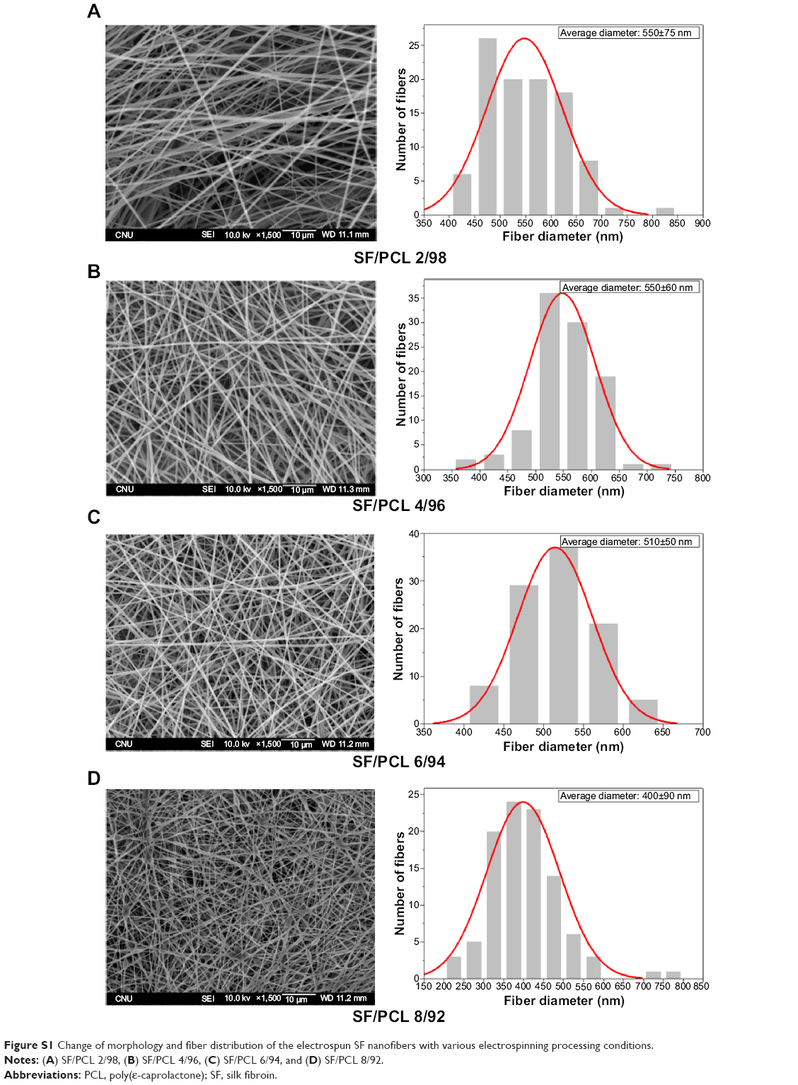 | Figure S1 Change of morphology and fiber distribution of the electrospun SF nanofibers with various electrospinning processing conditions. |
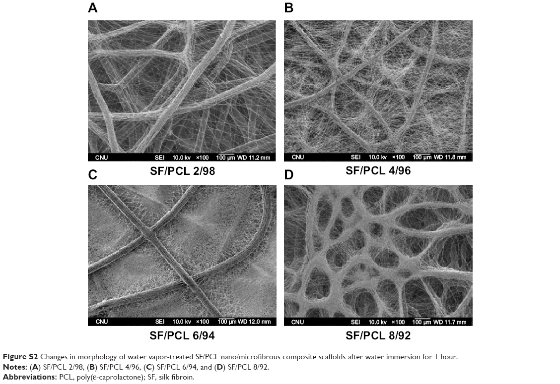 | Figure S2 Changes in morphology of water vapor-treated SF/PCL nano/microfibrous composite scaffolds after water immersion for 1 hour. |
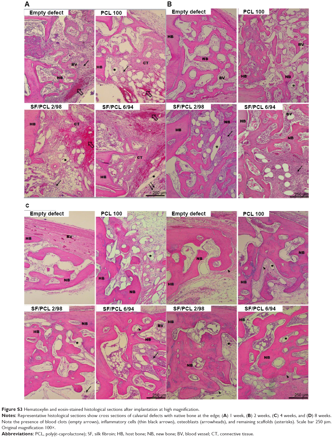 | Figure S3 Hematoxylin and eosin-stained histological sections after implantation at high magnification. |
 © 2015 The Author(s). This work is published and licensed by Dove Medical Press Limited. The full terms of this license are available at https://www.dovepress.com/terms.php and incorporate the Creative Commons Attribution - Non Commercial (unported, v3.0) License.
By accessing the work you hereby accept the Terms. Non-commercial uses of the work are permitted without any further permission from Dove Medical Press Limited, provided the work is properly attributed. For permission for commercial use of this work, please see paragraphs 4.2 and 5 of our Terms.
© 2015 The Author(s). This work is published and licensed by Dove Medical Press Limited. The full terms of this license are available at https://www.dovepress.com/terms.php and incorporate the Creative Commons Attribution - Non Commercial (unported, v3.0) License.
By accessing the work you hereby accept the Terms. Non-commercial uses of the work are permitted without any further permission from Dove Medical Press Limited, provided the work is properly attributed. For permission for commercial use of this work, please see paragraphs 4.2 and 5 of our Terms.